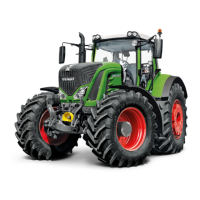
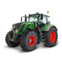
Do you have a question about the FENDT 900 Vario S4 Series and is the answer not in the manual?
General information and type approval assignment for FENDT tractor models.
Important safety guidelines, warnings, and position of safety decals on the vehicle.
Specifications for spanner sizes and tightening torques for various screws and bolts.
Information on approved fuels, lubricants, and their specific use instructions.
Detailed technical data, dimensions, and weights for FENDT tractor models.
General engine information, horsepower comparison, and common rail system description.
Procedures for engine faults, diagnostics, and component maintenance.
Procedures for valve adjustment and injector removal/installation.
Information on common rail systems, fuel pumps, and injectors.
Information on charge air systems, exhaust gas return, and after-treatment systems.
Technical drawings and procedures for the front axle assembly and components.
Functional diagrams and details of the front axle suspension.
Details on the VarioGuide steering system, hardware, and components.
Transmission function diagram and measurement procedures.
Procedures for dismantling, assembling, and adjusting the differential unit.
Disassembly and reassembly instructions for the final drive axle.
Instructions for removing and installing the rear wheel brake and actuator.
General information on compressed air pipes, tools, and torques.
Details on compressed air systems, components, and their functions.
Test report templates and functional plans for hydraulic pumps.
Function and technical details of LS pumps and other hydraulic pumps.
Component identification, sensor operations, and switch functionality.
Circuit diagrams for the basic control ECU (A050).
Procedures for measuring and testing electrical components labeled 'A'.
Procedures for measuring and testing electrical components labeled 'B'.
Procedures for measuring and testing the CAN bus system.
Procedures for measuring and testing electrical components labeled 'E'.
Procedures for measuring and testing electrical components labeled 'G'.
Procedures for measuring and testing electrical components labeled 'H'.
Procedures for measuring and testing electrical components labeled 'K'.
Procedures for measuring and testing electrical components labeled 'M'.
Procedures for measuring and testing electrical components labeled 'S'.
Procedures for measuring and testing electrical components labeled 'X'.
Procedures for measuring and testing electrical components labeled 'Y'.
Procedures for measuring and testing other electrical components.
Procedures for removing, attaching, and replacing cab components.
Operation and maintenance of the RÜFA reverse drive system.
Overview, adjustments, and controls for the driver's seat.
Information and procedures for the air-conditioning system and heating.
Details on hydraulic valves used in the front power lift system.
Slip control system and EPC valve functions for rear power lift.
Information and procedures for the lower link stabilizer.
Various assembly procedures and part kits for service.
List and description of special tools required for service tasks.




 Loading...