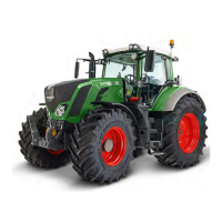
Do you have a question about the FENDT 800 Vario S4 Series and is the answer not in the manual?
| Max Speed | 50 km/h (31 mph) |
|---|---|
| Engine Type | AGCO Power engine |
| Transmission | Vario continuously variable transmission |
| Hydraulic System | Load sensing system |
| Tire Options | Various options available |
Detailed technical specifications including dimensions, weights, and performance data.
Lists and explains fault codes for the 800 and 900 Vario S4 series.
Procedures for calibrating various systems and sensors on the tractor.
Information on hydraulic brake systems, including warnings, diagrams, and service procedures.
Details on the front PTO valve block, transmission, drive, clutch, and pump.
Technical drawings and procedures for the rear PTO transmission and clutch.
General specifications, fault analysis, and special tools for the diesel engine.
Details on the fuel system, pressure checks, pumps, and components.
Operation, functional descriptions, and procedures for EPC valves and power lift controls.
Technical drawings and procedures for lower linkage support and stabilizer solenoid valves.
Circuit diagrams for the basic control ECU and functional description.
Procedures for measuring and testing various 'A' components, like instrument panel and ECU.
Procedures for measuring and testing various 'B' components, such as sensors.
Procedures for measuring and testing 'Y' components, such as solenoid valves.
 Loading...