8
EN
- the times when the tool is switched off or when
it is running but not actually doing the job, may
signicantlyreducetheexposurelevel
Protect yourself against the effects of vibration by
maintaining the tool and its accessories, keeping
yourhandswarm,andorganizingyourwork
patterns
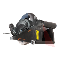
Your wall slotter has been designed for making
slots in masonry. The machine is only suitable for
right-hand use.
1. On/offswitch
2. Lock-offbutton
3. Lockingknobforslotdepth
4. Scale for slot depth
5. Spindle lock button
6. Guard
7. On/offswitchforlaser
8. Laser
9. Batterycompartment
10. Base
11. Guide roller
12. Dustextractionconnection
13. Maingrip
14. Auxiliary grip
4
Before assembly, always switch off the
machine and remove the mains plug
from the mains.
Worn or damaged cutting discs must be replaced
immediately.
2
- Onlyusesharpandundamagedcuttingdiscs.
- Onlyusecuttingdiscsthataresuitableforthe
material to be worked.
- Onlyusecuttingdiscswithamaximum
permitted speed that is equal to or exceeds
the maximum no-load speed of the machine.
- Onlyusediamondcuttingdiscsthatare
suitable for dry cutting.
- Always replace both cutting discs at the same
time.
- Never attempt to remove the guard.
● Placethemachineonastablesurface.
● LoosentheAllenscrews(15)usingtheAllen
key (16).
● Loosenthelockingknob(3)andlowerthe
base(10).
● Removetheguard(6).
● Keepthespindlelockbutton(5)pressedto
lock the spindle (17).
● Loosentheouterange(18)usingtheange
key(19).
● Removetheoldcuttingdisc(20),thespacers
(21), the old cutting disc (22), the spindle
sleeve(23),andtheinnerange(24).
Ifnecessary,usethesplittingwedge(25)to
remove the spacers (21).
● Ifnecessary,cleantheanges(18&24).
● Mounttheinnerange(24),thespindlesleeve
(23),thenewcuttingdisc(22),thespacers
(21),andthenewcuttingdisc(20).
● Firmlytightentheouterange(18)usingthe
angekey(19).
● Releasethespindlelockbutton(5).
● Mounttheguard(6).
● Raisethebase(10)andtightenthelocking
knob(3).
● FirmlytightentheAllenscrews(15)usingthe
Allen key (16).
The slot width can be set using the spacers
between the cutting discs. The number of spacers
between the cutting discs determine the slot width.
2
- Donotsettheslotwidthduringuse.
- Always mount at least one spacer between the
cutting discs.
● Determinetheslotwidth.
● Mountthespacers(21)aroundthecutting
discs(20&22)intherequiredorder.Referto
thechapter“Replacingthecuttingdiscs”.
Theslotdepthisvariablebetween0and28mm.
The slot depth can be read from the scale (4).
2
Do not set the slot depth during use.
● Slackenthelockingknob(3).
● Tiltthebase(10)totherequiredposition.Set
aslotdepthapproximately3mmdeeperthan
the required depth to compensate for possible
unevenness of the wall surface.
● Tightenthelockingknob(3).
 Loading...