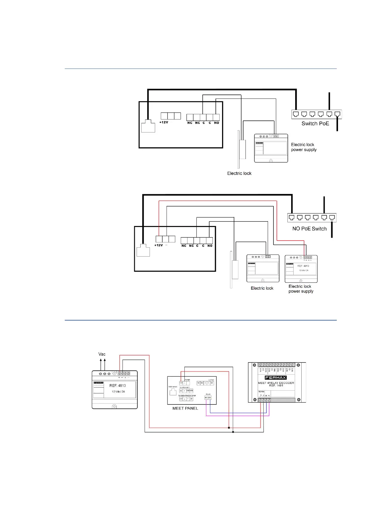
35
PoE Switch.
Use a power supply
adapted to the
electric lock voltage &
PoE switch
Supply the panel by
means of a FERMAX Ref.
4813 (12 Vdc 2A) power
supply
Use a power supply
adapted to the electric
lock voltage & current.
Do not power the panel
and the electric lock
from the same power
supply.
The panel has an internal tamper button. If the panel is separated from the wall, an alarm is
triggered in the panel, concierge and FERMAX MANAGENEMN SYSTEM (if exists).
4.4 Basic diagrams
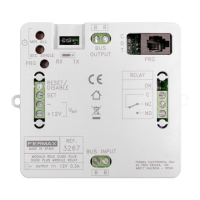
4.5 Diagram Installation of the 4 RELAY MODULE REF. 1491
This module is necessary if you want to use the function of activating from the monitors additional
relays (up to 4), for example to activate additional doors or gates.

 Loading...