11
If the unit does not pass a test, do not operate the unit. Under
no circumstance should you attempt to defeat the purpose of
the safety system.
Functional Tests
1. Check the unit for loose bolts, screws, nuts, etc.
2. Start the engine and check all the controls for proper
operation: ground speed control levers, parking brake,
throttle cable, electric PTO clutch, etc.
3. Stop the engine and check for fluid leaks: oil, fuel, and
hydraulic oil.
4. If any control fails to operate properly during testing or
seems to be out of adjustment, check and re-adjust it
according to the following Adjustment Procedures
section.
Safety Interlock System Checks
WARNING
DO NOT operate machine if any safety interlock or safety
device is not in place and functioning properly. Contact
your dealer immediately for assistance. DO NOT attempt to
defeat, modify, or remove any safety device.
TEST 1 - Engine must not crank if:
• PTO switch is engaged, OR;
• Parking brake is not engaged, OR;
• Ground speed control levers are not locked in their
NEUTRAL positions.
TEST 2 - Engine should crank if:
• PTO switch is not engaged, AND;
• Parking brake is engaged, AND;
• Ground speed control levers are locked in their
NEUTRAL positions.
TEST 3 - Engine must shut off if:
• Operator rises off seat with PTO engaged, OR
• Operator rises off seat with parking brake disengaged.
• Operator moves ground speed control levers out of their
neutral positions before disengaging parking brake.
TEST 4 - Check mower blade stopping time:
Mower blades and mower drive belt should come to a
complete stop within seven (7) seconds after electric PTO
switch is turned off (or operator rises off seat). If mower drive
belt does not stop within seven (7) seconds, see your dealer.
Note:Once the engine has stopped, PTO switch must be
turned off, parking brake must be engaged, and the ground
speed control levers must be locked in the NEUTRAL position
after the operator returns to the seat in order to start the
engine.
Adjustment Procedures
If any control fails to operate properly during testing or seems
to be out of adjustment, check and re-adjust it according to
the following instructions.
Seat And Ground Speed Control Lever
Adjustments
The seat and ground speed control levers should be adjusted
so that the ground speed control levers can be moved
through their full range of motion without contacting the
operator’s legs.
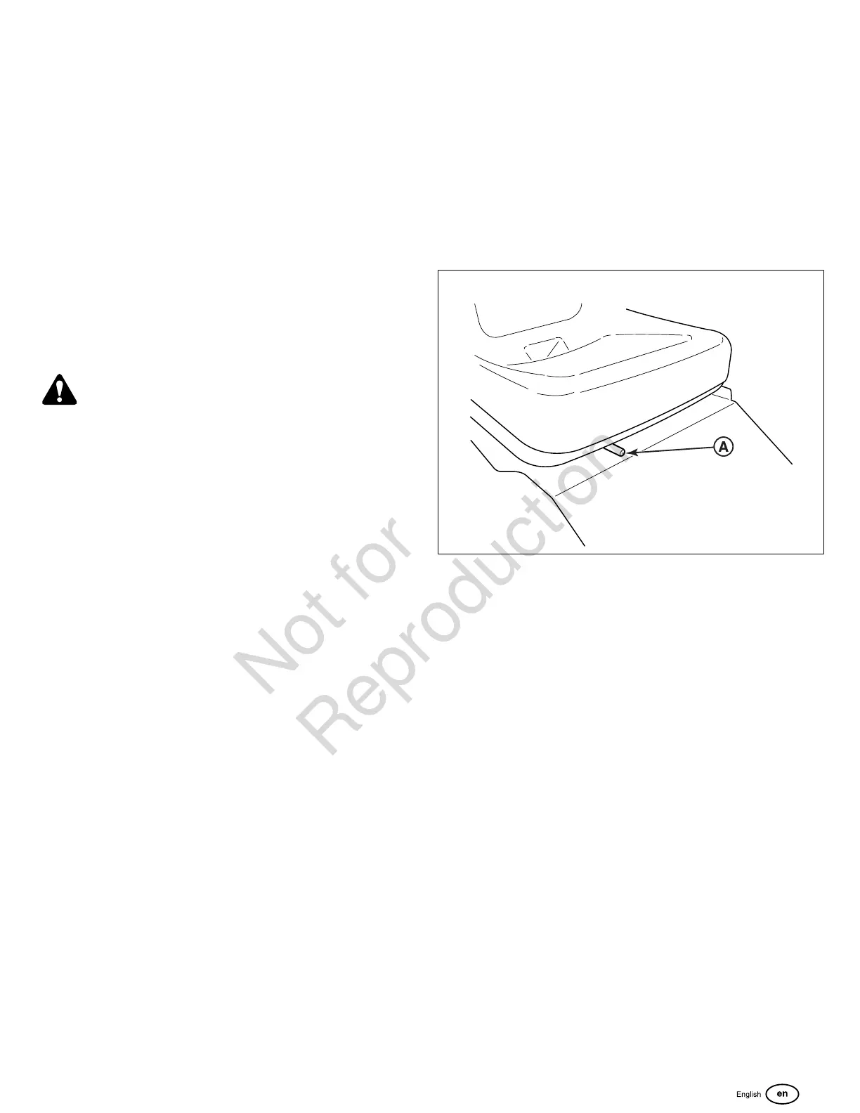
Seat Adjustment
The seat can be adjusted forward and back. Move the lever
(A, Figure 20) towards the left, position the seat as desired,
and release the lever to lock the seat into position.
20
Ground Speed Control Lever Adjustment
1. Loosen the ground speed control lever mounting
hardware (A, Figure 21) to adjust the levers forward and
backward.
2. Remove the hardware to raise or lower the levers.
3. Always be sure to adjust both levers so that they are
aligned (B, Figure 21).
4. After adjustment is complete, tighten the hardware to 13
lb-ft (18 Nm).

 Loading...