4 ferrismowers.com
3
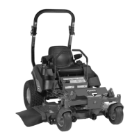
9. Center a jack underneath the rear bumper (E) of the
machine and raise the rear of the machine until the holes
in the bottom of the shocks align with the holes in the rear
suspension cradle (F).
10. Put the bolt through the washer, the shock, the rear
suspension cradle and secure using the nylock flange
nut. Repeat the process for the other side of the
machine.
11. Lower the rear bumper of the machine and remove the
jack.
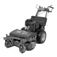
Connect the Battery Cables
WARNING
Battery acid can cause severe burns. Wear protective
gear when handling the battery.
Open flames and sparks can cause battery to explode.
BATTERY SAFETY RULES:
• Battery acid causes severe burns. Avoid contact with
skin.
• Wear eye protection when handling the battery.
• To avoid an explosion, keep flames and sparks away
from the battery, especially while charging.
• When installing the battery cables, connect the
positive (+) cable first and negative (-) cable last.
If not done in this order, the positive terminal can be
shorted to the frame by a tool.
1. Connect the red positive battery cable (B, Figure 1)
to the positive battery post. Make sure that the cable
boot completely covers the positive terminal, so that the
terminal cannot touch the insulator pad (C).
4
2. Connect the black negative battery cable (A) to the
negative battery post.
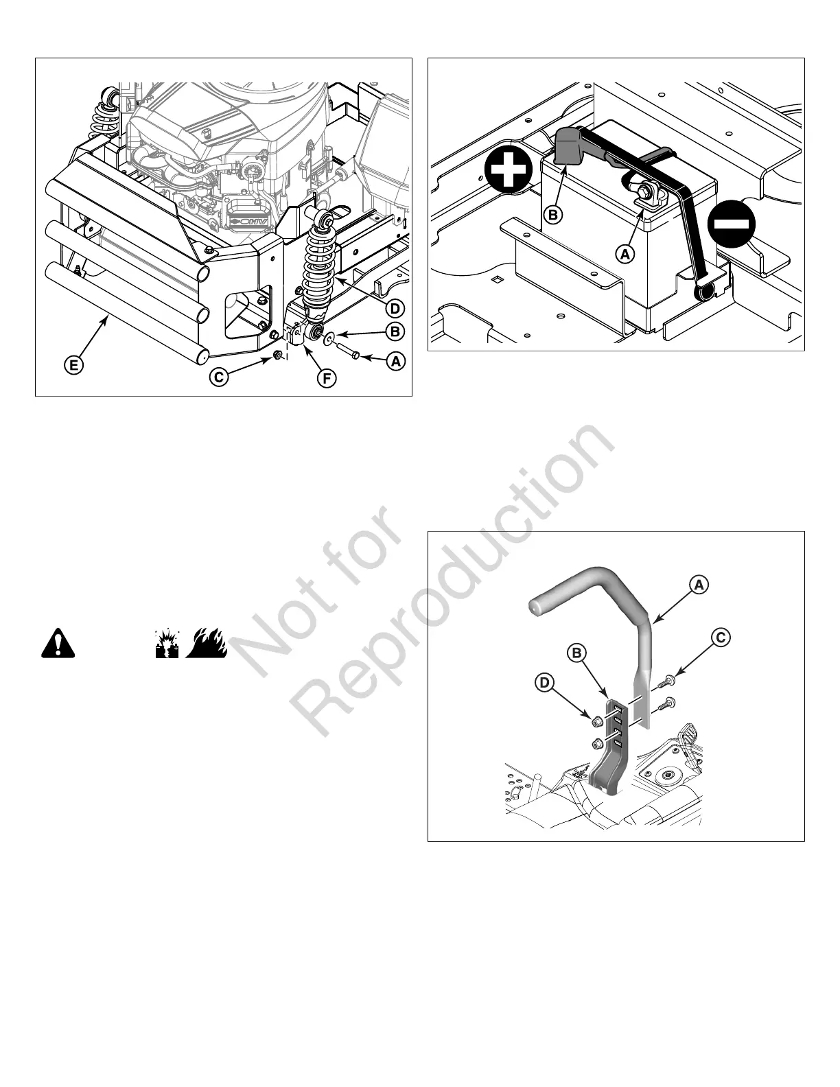
Install the Ground Speed Control Levers
This procedure is only necessary if the ground speed control
levers are not factory-installed on your unit.
1. Install the ground speed control lever (A, Figure 5) to the
control lever base (B) using the bolts (C) and nuts (D) that
were included with the levers.
5
2. Repeat the process on the other side of the unit.
3. Align the control levers with each other and then tighten
the mounting hardware to 13 lb-ft (18 Nm).
Install the Seat
This procedure is only necessary if the seat is not factory-
installed on your unit.
1. Unpack the seat.
2. Install the seat (A, Figure 6) onto the seat mount plate (B)
with the retaining nuts (C) provided. Hand tighten the four
(4) retaining nuts.
 Loading...