Do you have a question about the Ferroli DIVA C24 and is the answer not in the manual?
Details on boiler operation, controls, and settings.
Mandatory requirements for qualified personnel and compliance with regulations.
Requirements for the boiler's installation environment, ventilation, and clearances.
Instructions for connecting water pipes, including safety valve and system characteristics.
Procedures for connecting gas supply and electrical power, including safety aspects.
How to adjust boiler settings like heating power and lighting power.
Requirements for air intake and flue gas exhaust systems.
Steps to convert the boiler for different gas types.
Checks and steps required before and during initial boiler lighting.
Diagnostic system, fault codes, and possible causes/cures for boiler issues.
List of components referenced in diagrams and tables.
Diagrams showing boiler dimensions and connection points.
Diagrams illustrating the overall boiler layout and key parts.
Diagrams illustrating the heating and DHW water circuits.
Comprehensive table of the boiler's technical specifications and performance data.
Graphs showing boiler pressure versus power output.
Graphs illustrating flow rate versus pressure for the circulating pump.
A schematic showing electrical connections for the control board and components.
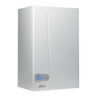
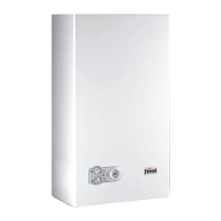
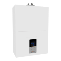
| Type | Combi Boiler |
|---|---|
| Power Output | 24 kW |
| Fuel Type | Natural Gas / LPG |
| Energy Efficiency Class | A |
| Mounting | Wall Mounted |
| NOx Class | 5 |
| Max. Working Pressure | 3 bar |
| Water Pressure | 0.2 - 8 bar |
| Dimensions (H x W x D) | 700 x 400 x 299 mm |
| Gas Consumption | 2.73 m³/h |





 Loading...