DIVA C24 / C28 / C32
14
EN
cod. 3541E032 - Rev. 00 - 02/2014
4.2 Startup
Before lighting the boiler
• Check the seal of the gas system.
• Check correct prefilling of the expansion tank.
• Fill the water system and make sure all air contained in the boiler and the system
has been vented.
• Make sure there are no water leaks in the system, DHW circuits, connections or boiler.
• Check correct connection of the electrical system and efficiency of the earthing system.
• Make sure the gas pressure for heating is that required.
• Make sure there are no flammable liquids or materials in the immediate vicinity of
the boiler
Checks during operation
• Switch the unit on.
• Check the tightness of the fuel circuit and water systems.
• Check the efficiency of the flue and air/fume ducts while the boiler is working.
• Make sure the water is circulating properly between the boiler and the systems.
• Make sure the gas valve modulates correctly in the heating and domestic hot water
production stages.
• Check correct boiler lighting by performing various tests, turning it on and off with
the room thermostat or remote control.
• Make sure the fuel consumption indicated on the meter matches that given in the
technical data table in cap. 5.
• Make sure that with no demand for heating, the burner lights correctly on opening a
hot water tap. Check that in heating mode, on opening a hot water tap, the heating
circulating pump stops and there is regular production of hot water.
• Make sure the parameters are programmed correctly and carry out any required
customisation (compensation curve, power, temperatures, etc.).
4.3 Maintenance
Periodical inspection
To ensure proper operation of the unit over time, have qualified personnel carry out a
yearly inspection, providing for the following checks:
• The control and safety devices (gas valve, flow switch, thermostats, etc.) must func-
tion correctly.
• The fume exhaust circuit must be perfectly efficient.
(Sealed chamber boiler: fan, pressure switch, etc. - The sealed chamber must be
tight: seals, cable glands, etc.)
(Open chamber boiler: anti-backflow device, fume thermostat, etc.)
• The air/fume terminal and ducts must be free of obstructions and leaks
• The burner and exchanger must be clean and free of deposits. Do not use chemical
products or wire brushes to clean.
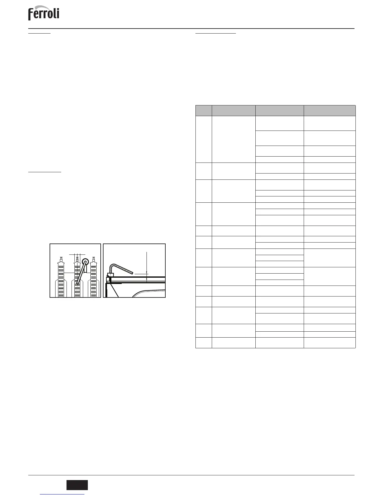
• The electrode must be properly positioned and free of deposits.
fig. 10 - Electrode positioning
• The gas and water systems must be tight.
• The pressure of the water in the system when cold must be approx. 1 bar; otherwise,
bring it to that value.
• The circulating pump must not be blocked.
• The expansion tank must be filled.
• The gas flow and pressure must match that given in the respective tables.
4.4 Troubleshooting
Diagnostics
The boiler is equipped with an advanced self-diagnosis system. In case of a boiler fault, the
display will flash together with the fault symbol (detail 11 -
fig. 1
) indicating the fault code.
There are faults that cause permanent shutdown (marked with the letter "A"): to restore
operation, press the RESET button (detail 6 - fig. 1) for 1 second or RESET on the op-
tional remote timer control if installed; if the boiler fails to start, it is necessary to eliminate
the fault.
Faults marked with the letter "F" cause temporary shutdowns that are automatically reset
as soon as the value returns within the boiler's normal working range.
Table of faults
Table. 2 - List of faults
Fault
code
Fault Possible cause Cure
A01
No burner ignition
No gas
Check the gas flow to the boiler and
that the air has been eliminated from
the pipes
Ignition/detection electrode fault
Check the wiring of the electrode
and that it is correctly positioned and
free of any deposits
Faulty gas valve
Check the gas valve and replace it if
necessary
Ignition power too low Adjust the ignition power
A02
Flame present signal with
burner off
Electrode fault
Check the ionization
electrode wiring
Card fault Check the card
A03
Overtemperature protection
activation
Heating sensor damaged
Check the correct positioning and
operation of the heating sensor
No water circulation in the system Check the circulating pump
Air in the system Vent the system
F04
Fume thermostat intervention
(after intervention of the fume
thermostat, boiler operation is
prevented for 20 minutes)
Fume thermostat contact open Check the thermostat
Wiring disconnected Check the wiring
Flue obstructed or not correctly
sized
Check the flue
F05
Card parameter fault Wrong card parameter setting
Check the card parameter
and modify it if necessary
A06
No flame after the ignition
phase
Low pressure in the gas system Check the gas pressure
Burner minimum pressure setting Check the gas pressures
F10
Delivery sensor fault
Sensor damaged
Check the wiring or replace
the sensor
Wiring shorted
Wiring disconnected
F11
DHW sensor fault
Sensor damaged
Check the wiring or replace
the sensor
Wiring shorted
Wiring disconnected
A23
Card parameter fault Wrong card parameter setting
Check the card parameter
and modify it if necessary
A24
Card parameter fault Wrong card parameter setting
Check the card parameter
and modify it if necessary
F37
Incorrect system
water pressure
Pressure too low Fill the system
Water pressure switch damaged
or not connected
Check the sensor
F43
Exchanger protection
activation.
No system H
2
O circulation
Check the circulating pump
Air in the system Vent the system
F50
Controller
DBM32
fault Controller
DBM32
internal error
Check the ground connection and
replace the controller if necessary.