15
GN3
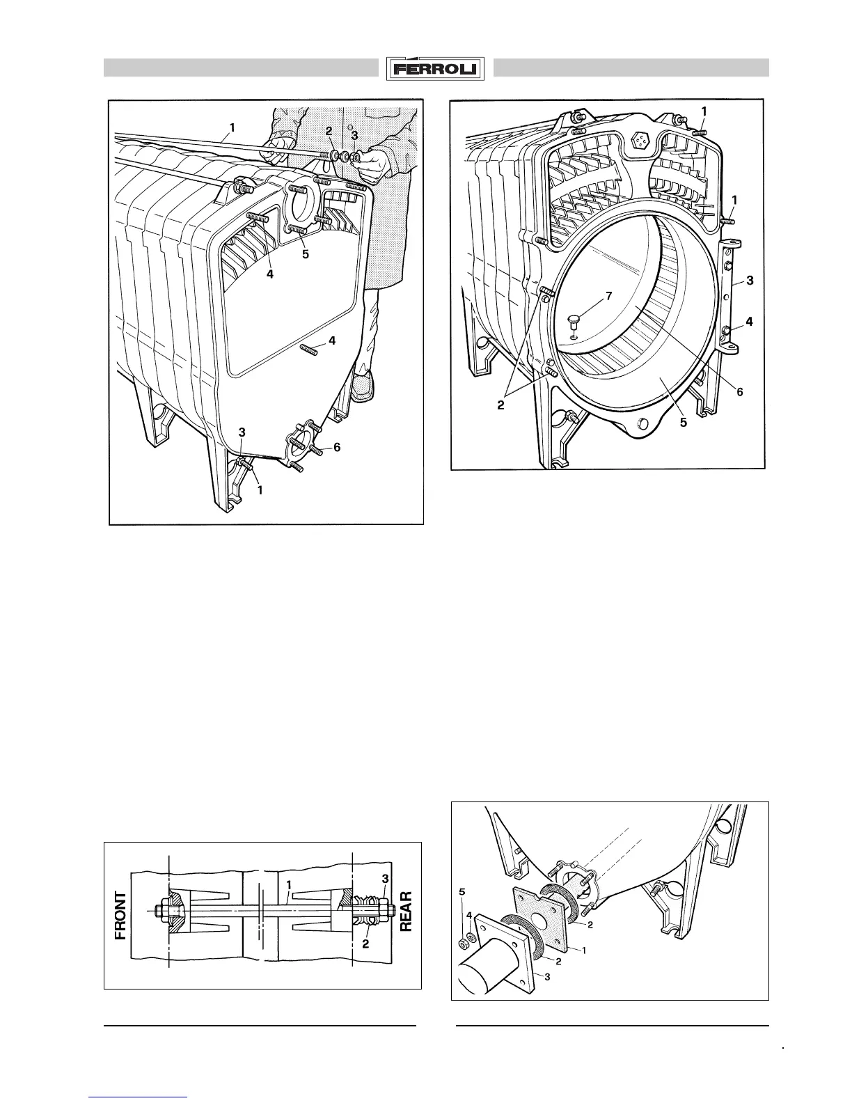
Fig. 24
Fig. 26
as to crush them.
13. (Fig. 26) Mount the following parts on the front side of
the boiler shell:
* Four stud bolts 1 (M12x80) of the upper door.
* Two stud bolts 2 (M12x135) of the door closing handw-
heels.
* Door support 3, fixing it with the two screws 4.
Place the cylinder (6) in the combustion chamber
according the indications in fig. 8 (complying with
dimension in table) insert the pin in the cylinder hole.
14. (Fig. 27) Mount distribution pipe 1, if necessary in
parts interspaced with a seal 2.
Check that the notch on the flange points upwards so that
the water through holes are pointing downwards. Mount
the second seal 2, flange 3, washers 4 and then tighten
with nuts 5.
10. Proceed as described in the previous paragraph until
all the elements forming the boiler shell have been
mounted.
11. (Fig. 24-25) Mount the four rods “1”, the six Belleville
washers “2” in the rear part of the boiler shell, then tighten
nuts “3”.
12. (Fig. 24) Mount the following parts on the rear side of
the boiler shell:
* Three stud bolts 4 (M12x100) of the smokebox.
* Four stud bolts 5 (M16x65) of the upper flange.
* Four stud bolts 6 (M16x75) of the lower flange.
Mounting the rods with the Belleville washers (fig. 25)
NOTE: The springs must be mounted opposite, as shown
in the drawing, and the nuts must not be fixed so strongly
Fig. 25
Fig. 27






 To Next Page