22
GN3
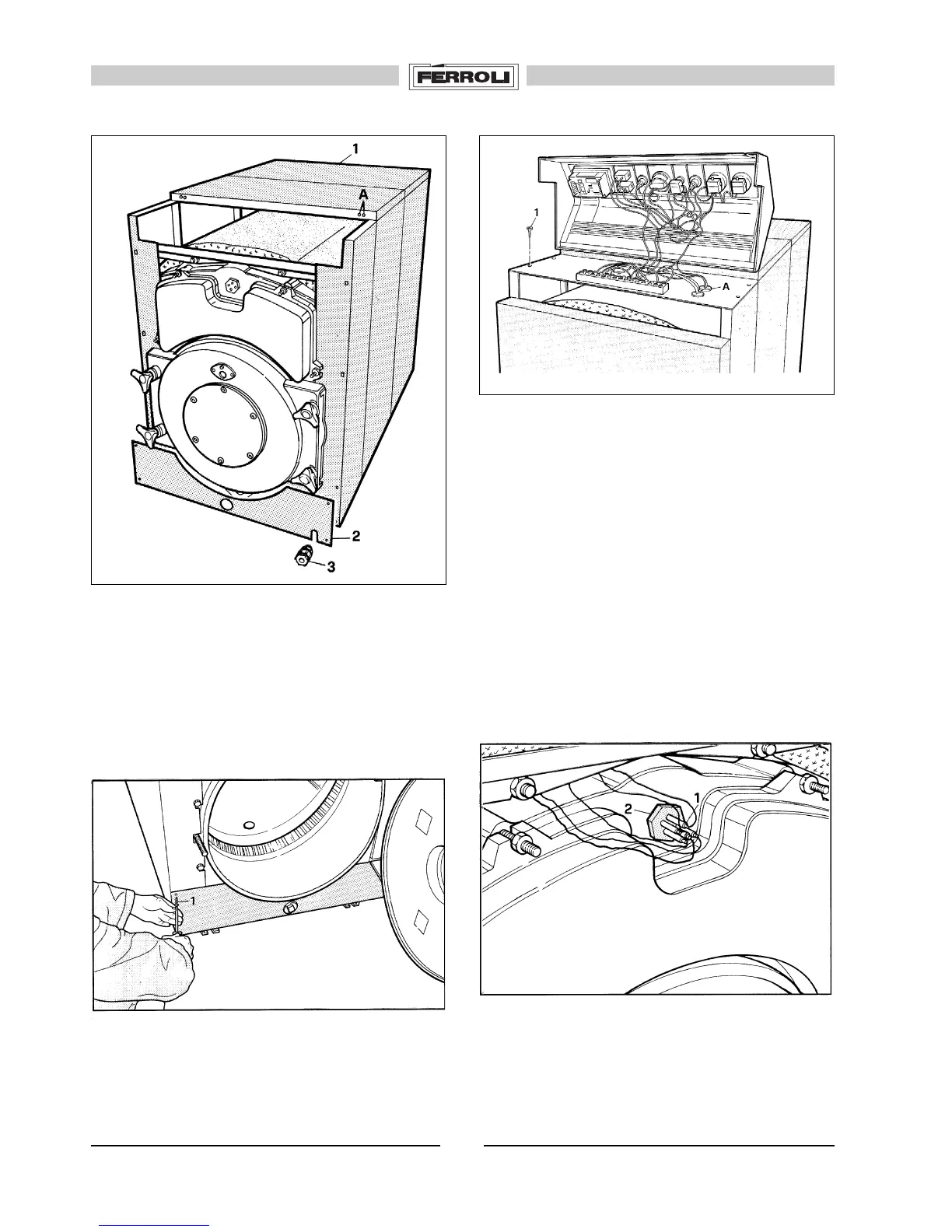
34. (Fig. 46) Mount the control panel, fixing it with the four
self-threading screws 1.
Allow the four wires (thermometer, safety thermostat and
regulating thermostat) to pass through hole A and make
the electrical connections as indicated in the diagram of
fig. 6.
Note: The electrical connections between the burner and
boiler must be carried out by Qualified Personnel.
33. (Fig. 45) Fix lower front panel 2 using the four self-
threading screws 1.
35. (Fig. 47) Unravel the wires and insert the four probes
1 into sheath 2.
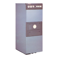
32. (Fig. 44) Mount upper panels 1 according to the size
of the boiler, remembering to ensure that outlets A point
towards the front part of the boiler.
Prepare lower closing panel 2, mounting core hitch 3 for
the burner cable.
Fig. 45
Fig. 46
Fig. 47
Fig. 44
 Loading...