Supplied By www.heating spares.co Tel. 0161 620 6677
11
DOMINA F 24 - 30 E
FERELLA F 24 - 30 MEL
MILOS AIR COMPACT E
Version - 09.2002
2. PRODUCT FRAMEWORK AND INTERNAL
COMPONENTS
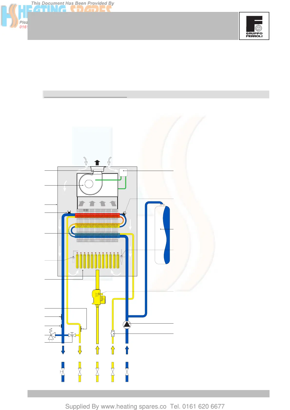
2.1 Hydraulic circuit heating
Hydraulic diagram for heating
When there is a call for heat, the room thermostat or control system make the burners ignite and the
circulation pump come into operation. The heat contained in the products of combustion is transferred
to the water by the system via the exchanger. For more details on the operating logic, refer to chap.3.
Key
5 Airtight chamber
7 Gas inlet
8 Tap water outlet
9 Tap water inlet
10 System delivery
11 System return
14 Safety valve
16 Fan
20 Burner unit
27 Heat exchanger
29 Fume outlet collar
32 Heating circulator
34 Heating temperature sensor
42 Tap water temperature
sensor
43 Air pressure switch
44 Gas valve
49 Safety thermostat
50 Heating thermostat
56 Expansion tank
74 Heating system cock
81 Ignition electrode
82 Detection electrode
114 Water pressure switch
136 Flow meter
187 Fume diaphragm
11
10
-
+
7
8
9
43
50
56
81
44
32
49
20
82
27
5
29-187
16
74
14
114
34
136
42






 To Next Page