201
15
Note - To mount the boiler on the wall, a two person lift will be needed.
1.0 UNPACKING
The appliance is delivered in two cartons.
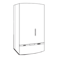
1.1 The large carton contains the boiler, and the Installation/Servicing and Users Instruction.
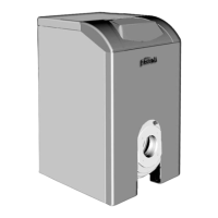
1.2 One carton contains the mounting jig assembly, complete with isolating valves, the assembly fixing
screws and wall plugs (x4), the boiler mounting nuts and washers (x2) and drilling template.
When the cartons are unpacked examine for any signs of damage in transit.
All protective plastic should be left in place until installation is complete.
2.0 FIXING THE MOUNTING JIG ON THE WALL
2.1 Select the boiler location carefully ensuring that alla requirements given in previous text are satisfied.
Fig. 3 will also give guidance to fixing dimensions.
2.2 Locate template on wall, mark the positions of the four jig bracket fixing holes.
2.3 Using a 10 mm drill, drill 70 mm deep holes to accept the wall plugs, and insert wall plugs.
2.4 Fit the mounting jig assembly using the four fixing screws provided
(Ensure that all the service cocks are in the OFF position).
2.5 With the exception of the connection to the pressure relief valve, make all the water and gas
connections to the jig bracket valves. Fully tighten (fig. 9). Before the gas inlet to the boiler there must
be at least 100 mm of straight before any bends, to allow access to the union nut.
Important Note - Always use two spanners to prevent twisting of soft copper pipework on the boiler.
Flush out the water system.
Note - The maximum inlet cold water pressure must not exceed 10 bar (145 P.S.I.) and a water
governor or a pressure reducing valve will be required if the pressure is in excess of 5 bar (72 P.S.I.).
Ensure all pipework is adequately supported.