201
13
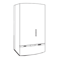
Installation of boiler
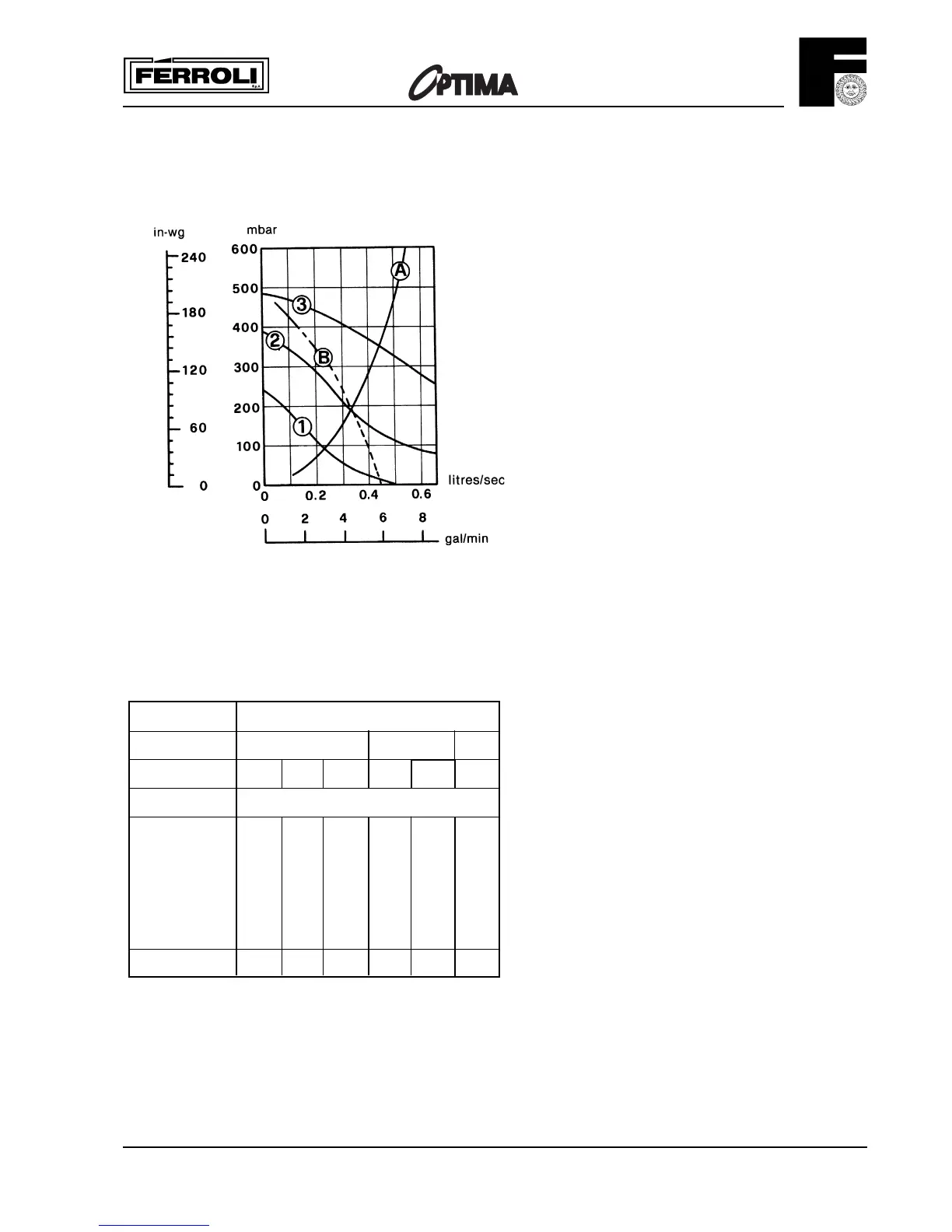
1 2 3 Speed settings
A Boiler pressure drop
B Max. available pump head C.H.
Fig. 7
SAFETY VALVE
SETTING (bar)
VESSEL CHARGE
PRESSURE (bar)
INITIAL SYSTEM
PRESSURE (bar)
TOTAL WATER
CONTENT of SYSTEM
3.0
0.5 1.0 1.5
1.0 1.5 2.0 1.5 2.0 2.0
EXPANSION VESSEL VOLUME (litres)
LITRES
25 3.5 6.5 13.7 4.7 10.3 8.3
50 7.0 12.9 27.5 9.5 20.6 16.5
75 10.5 19.4 41.3 14.2 30.9 24.8
100 14.0 25.9 55.1 19.0 41.2 33.1
125 17.5 32.4 68.9 23.7 51.5 41.3
150 21.0 38.8 82.6 28.5 61.8 49.6
175 24.5 45.3 96.4 33.2 72.1 57.9
200 28.0 51.8 110.2 38.0 82.4 66.2
0.140 0.259 0.551 0.190 0.412 0.33
For syst. volumes other than
those given above, mult. the syst.
volume by the factor across
SIZING OF ADDITIONAL EXPANSION VESSELS:
Deduct from the value given in the table the 7 litre vessel supplied.
Note
1. Fill C.H. installation to min. 1.5 bar.
2. Select by preference the expansion vessel for increased
system pressure of 2.0 bar
3. Expansion vessel must be fitted to Central Heating Return
Inlet
4. The standard 7 litres expansion vessel is charged to 1 bar
Fig. 8