201
19
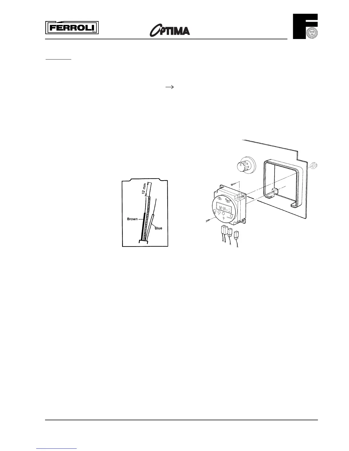
Fig. 14
Over ride
By pressing the over ride button (E) the timer programme is over ridden ie, if programme is in OFF
time it will come ON and if in ON time will go OFF.
The timer will revert back to it set programme on reaching the next ON or OFF time.
When the programme is on over ride the sign will be shown in the display window (B).
Reset Button
By the use of a pencil the reset button can be pushed (R). This will clear all programmes apart from
those factory pre set.
Reset is only possible with switch (A) in set Clock position!
x
12.0 REMOVAL OF THE CLOCK
a) Refer to section 1, items a, c, d, f and j.
b) Disconnect the electrical connections to the time clock.
c) Remove the time clock from the control panel (fig. 43).
d) Re-assemble in reverse order (refer to fig. 43 for replacement of
the time clock).
4.1 Procedure
4.1.1 The supply cable must not be no less than 0.75 mm (24x0.2
mm) to BS6500 table 16.
4.1.2 The earth conductor must be cut longer than the live and neutral (fig. 14).
Connect the Supply Cable to the terminal block marked 240 V ~ 50 Hz, L, N, the supply cable is to be connected
as follows:
i) Connect the brown wire to the L (live) terminal).
ii) The blue wire to the N (neutral) terminal.
iii) The green/yellow wire to the (earth) terminal.
4.1.3 Secure the cable with the cable clamp.
The supply cable can be connect to the mains supply by the use of an unswitched shuttered socket-outlet in
conjunction with the 3A fused 3 pin plug both in accordance with BS 1363. This provides complete isolation.
Alternatively, a fused double pole switch having a contact separation of at least 3 mm, in all poles and provided
just for the boiler and its external controls can be used.
A wiring diagram is provided on the appliance, attached to the rear of the front panel. In addition, there is
one in this manual (fig. 20b).
Attention is drawn to the requirements of the current I.E.E. Regulation and in Scotland, the electrical provisions
of the Building regulations.
4.2 Room Thermostat (fig. 18) (or remote time clock connection)
4.2.1 Please note that the room thermostat, clock switch connection is 24 V.
To connect mains voltage to these terminals will seriously damage the printed circuit board.
The room thermostat and clock switch connector block is situated within the connector box. Twin core cable
should be used for this connection (terminals 4 and 5).
4.2.2 If using a remote 240 Volt time clock ensure that the motor and switch connections are totally separate in
the clock and that the switch connections are independent for the 24 Volt terminals (4 and 5) on the boiler.