2 Product Overview
16 Festo – GDCP-CMMD-AS-HW-EN – 1404NH – English
Warnings are automatically acknowledged when the cause is no longer present. Error
messages are ac knowledged via:
– the parameterisation software FCT
– the fieldbus (contro l word)
– or a decreasing edge at [ X1.1/2] DI N5.
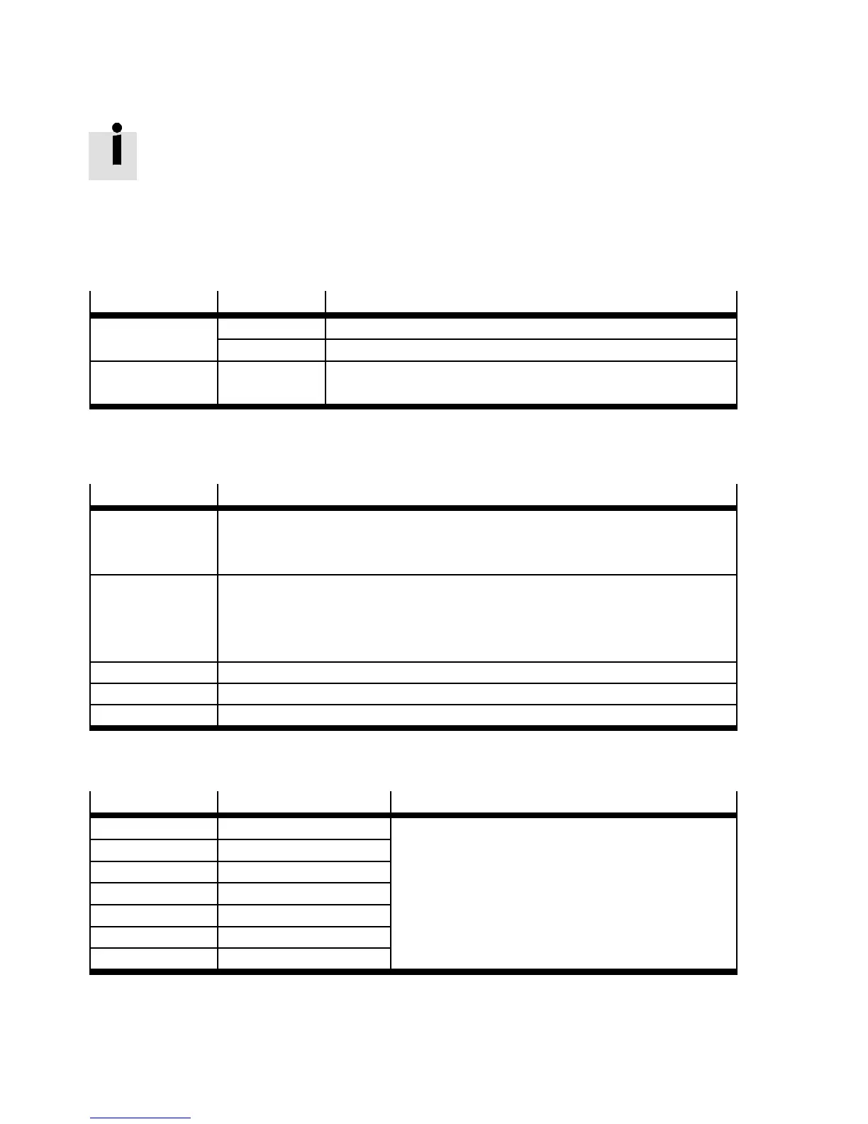
2.4.2 LED indicators
LED
LED colour Function
Ready Green Operating status/controller enable
Flashing green Parameter file *.DCO (me mory card) is being read/written
Bus Yellow Bus status display lights up whenever CAN communication is
taking place
Tab. 2.3 LED sta tus indicator ( Fig. 2.2 1 )
2.4.3 DIL switch
DIL switch
Function
S1.1 … 7 Bus address or MAC-ID on first axis Example Tab. 2.5
The second axis gets the address of the first axis +1
NodeNumber Slave = NodeNumberMaster +1
S1.8 Automatic loading of a new firmware file from the memory card by the start pro-
gramme (bootloader):
1)
– ON: Download from the SD memory card to the motor controller.
– OF F: No download.
S1.9 … 10 Setting the bus transmission rate Example Tab. 2.6
S1.11 Activation of the CAN-bus interface
S1.12 Terminating resistor for CAN-bus
1) Addi ti o n al inf o r mati o n can be foun d in the fir mw are dow n lo ad Description of functions and commissioning, GDCP-CMMS/D-FW-....
Tab. 2.4 Function of the DI L switches ( Fig. 2.2 3 )
S1.1 … 7
ON/OFF ( ex ample) Significance
1)
1 ON 1 DIL switch S1.1 is the low-order bit.
Example: address = 1011011 =91
2 ON 1
3 OFF 0
4 ON 1
5 ON 1
6 OFF 0
7 ON 1
1) Additional information Description of functions and commissioning, GDCP-CMMS/D-FW-....
Tab. 2.5 CAN bus address or MAC-ID
 Loading...