4 Electrical installation
Festo – GDCP-CMMD-AS-HW-EN – 1404NH – English 25
4.2 .2 EMC-compliant wiring
Routing cables:
– Do not run signal cables parallel to power cables
– The distance between signal cables and power cables should be at least 25 cm
– Avoided crossing power cables or running them at a 90° angle.
Screening:
– Always run motor and encoder cables so they are screened
– Twist unscreened signal cables
– When using screened cables with an unscreened plug housing: the maximum length of
the unscreened wires at the end of the cable is 35 mm.
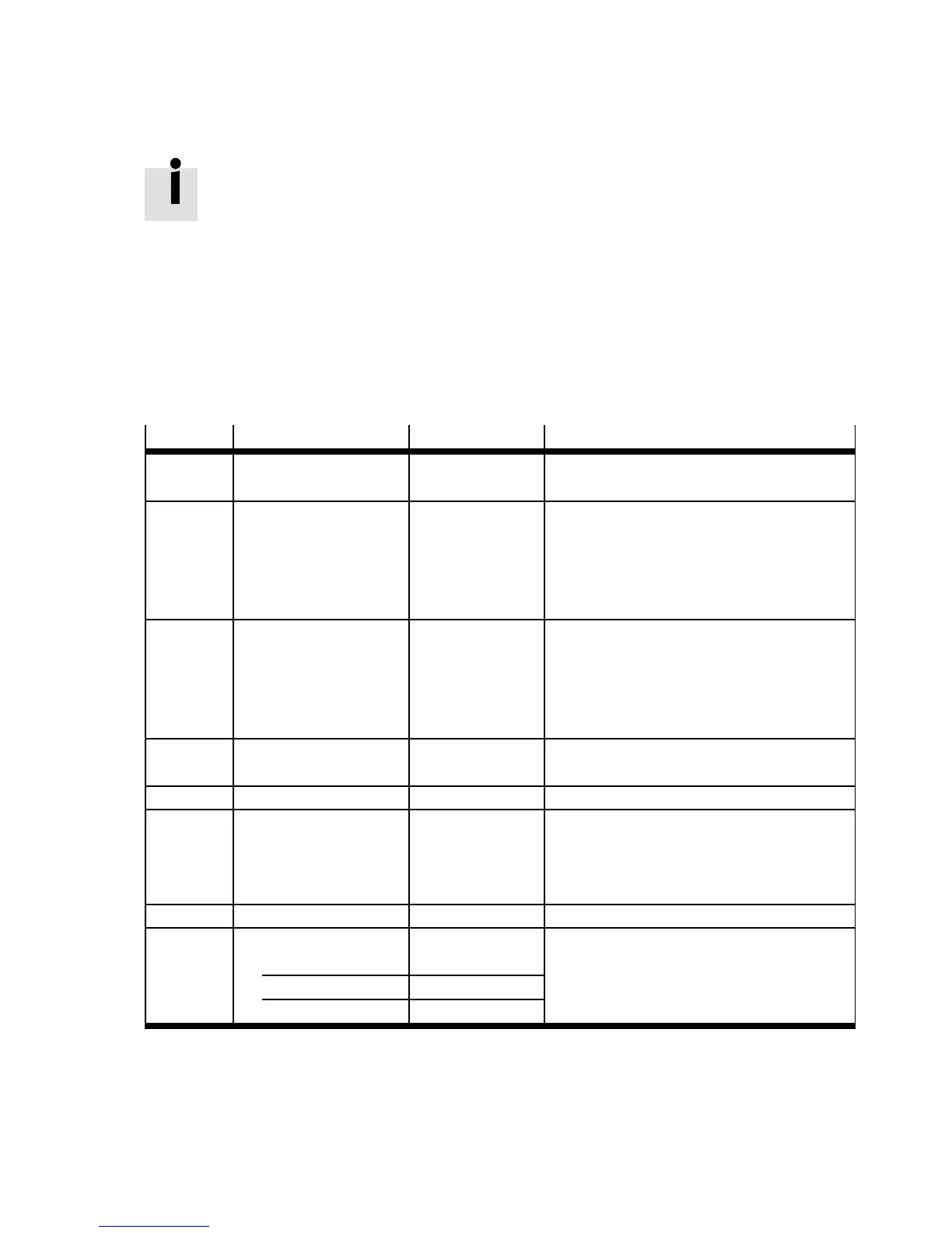
• Observe the permissible cable lengths and th e required screening for t he cables Tab. 4.3.
Port
Interface Cable length [m] Screening
[X1.1]
[X1.2]
I/O interface, axis 1
I/O interface, axis 2
≤ 5 Recommendation: screened
[X2.1]
[X2.2]
Encoder axis 1
Encoder axis 2
≤ 25 – Screened
– A pply the cable screening of the en-
coder c able flat on the plug housing of
the encoder connection [X2 1/2]
Chapter 4.4
[X3.1]
[X3.2]
STO interface axis 1
STO interface axis 2
≤ 30 When wiring outside the control cabinet:
– Use screened cable
– Guide screening into the control cabin-
et and attach to the side of the c ontrol
cabinet.
[X4] CAN ≤ 40
1)
–
[X5] RS232/RS485 ≤ 5 Screened
[X6.1]
[X6.2]
Motor axis 1
Motor axis 2
≤ 15
2)
– Screened
– Apply cable screening to the shield con-
nection terminal of the corresponding
motor controller Chapter 4.8.3
[X9] Power supply ≤ 2 –
[X10.1]
[X10.2]
Master/Slave axis 1
Master/Slave axis 2
Screened
as input (slave) ≤ 30
as output (master) ≤ 5
1) Permitted total line length of field bus at a bit rate of 1 Mbit/s. Observe details in the documentation of your control system or bus
interface.
2) With additional EMC filter: cable length up to 25 m Tab. 4.2.
Tab. 4.3 EMC-compliant wiring
 Loading...