Do you have a question about the Festo CMMP-AS-C2-3A and is the answer not in the manual?
Lists all related manuals for the CMMP-AS product family.
Details the items included in the standard delivery package.
Explains the meaning of icons used to convey warnings and notes.
Provides essential guidance and liability information for safe operation.
Highlights risks and consequences associated with improper operation or handling.
Covers general warnings, standards compliance, and approved parts.
Details safety measures required during installation and maintenance procedures.
Warns about electrical hazards and provides precautions for safe interaction.
Explains safety standards for low voltage connections and protection.
Addresses risks of unexpected motor movements and necessary safety measures.
Advises on hazards from hot surfaces and necessary cooling periods.
Outlines safety precautions for handling and assembling the device to prevent injury.
Provides an overview of the CMMP-AS series, type codes, and key features.
Details the timing and steps involved from power-on to operational readiness.
Explains the single-phase AC supply requirements and active PFC stage.
Describes connecting intermediate circuits and direct DC power supply options.
Specifies requirements for the mains power supply circuit breaker.
Explains the integrated brake chopper and its connection for braking resistors.
Lists available communication interfaces like RS232, CANopen, Profibus, etc.
Describes the FHPP data profile for standardized control and programming.
Details the RS232 interface for parameterization and test control.
Covers CANopen and FHPP profiles available for CAN bus communication.
Describes PROFIBUS communication support according to DP-V0 and Profidrive.
Explains DeviceNet communication, its profile, and EDS file usage.
Details SERCOS module connection for CNC controllers and synchronisation.
Covers digital and analogue inputs/outputs for control functions and target selection.
Discusses supported motor types, including synchronous servo and linear motors.
Outlines the controller's functionalities and compatibility with previous series.
Compares the control structure, interfaces, and parameters with the SEC-AC family.
Explains PWM clock frequency settings and sinewave modulation types.
Details how setpoints can be specified using analogue inputs and fixed values.
Describes operation in torque control mode where current regulator is active.
Explains maintaining constant motor speed regardless of load, using speed regulation.
Covers operation with torque limitation and speed regulation characteristics.
Discusses synchronizing device regulation with external clock signals via PLL.
Explains acquiring and storing holding torque for vertical axes to improve starting.
Details positioning modes, including jerk-limited and time-optimised control.
Describes master-slave mode (synchronisation) and electrical gearbox functionality.
Explains direct control of a holding brake and automatic braking functions.
Introduces positioning control, target tables, and movement profiles.
Explains positioning by adding to the current position without a fixed zero point.
Describes positioning to a fixed absolute position relative to a zero point.
Details time-optimised and jerk-limited positioning profiles with acceleration/braking.
Explains the requirement for a zero point and how the controller performs homing.
Covers sequential positioning records and path program creation.
Describes using an optional stop input to interrupt or resume positioning.
Explains specifying setpoints in multi-axis applications using linear interpolation.
Details clock synchronisation for simultaneous motion in multi-axis applications.
Covers "Safe standstill" function and protection against unexpected motion per EN 954-1.
Explains the "Safe standstill" function for preventing dangerous mechanical motion.
Provides details on implementing "Safe standstill" with circuit breakers and pulse blockers.
Details the secure control of the holding brake via two channels for safety.
Illustrates the functional method of "Safe standstill" with controller enabling and stopping brake.
Presents typical application examples, such as emergency stop circuits.
Explains protective door monitoring for safety, stopping the drive when doors are open.
Provides key guidelines for mounting the controller in control cabinets.
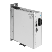
Identifies the components and connections on the front view of the CMMP-AS controller.
Describes the mounting clips and the process for attaching the controller to a mounting plate.
Details the wiring connections for power supply, motor, and holding brake.
Lists the necessary components for operating a complete CMMP-AS system.
Covers layout, counterplug, and pin assignments for the power supply connector.
Guides on using software to calculate the appropriate braking resistor.
Details layout, counterplug, and pin assignments for the motor connection.
Provides pin assignments for the motor connection connector.
Explains the functions of digital and analogue I/Os and their connections.
Provides a detailed pinout for the I/O communication connector.
Offers important notes for connecting the I/O interface, including signal levels.
Links to the description of the "Safe standstill" safety function.
Provides pin assignments for the Safe Standstill / Supply 24V connector.
Details the connection for resolver feedback signals, including layout and pin assignments.
Details the connection for encoder feedback signals.
Explains how to connect incremental encoders for input signals.
Explains how to connect incremental encoders for output signals to control systems.
Details CAN bus connection, including layout, counterplug, and pin assignments.
Covers RS232/COM connection, including layout and counterplug.
Provides pin assignments for the RS232/COM interface.
Covers safety and EMC requirements for installation.
Details how to connect PE cables and shields for safety and EMC compliance.
Explains EMC principles and how they relate to servo drive controller design.
Defines EMC environments and requirements for motor cable lengths.
Provides guidelines for wiring to minimize interference and ensure EMC compliance.
Offers recommendations for applications using long motor cables and filters.
Warns about ESD hazards from unused connector pins and device isolation.
Emphasizes reading EMC-compliant wiring instructions before connecting cables.
Lists the tools and materials required for startup procedures.
Guides on connecting the motor cable, plugs, and shields.
Details steps for connecting the controller to the power supply and 24V pack.
Outlines the procedure for connecting a PC via the serial interface cable.
Explains how to verify readiness using the READY LED and segment display.
Describes the controller's sensors and monitoring functions for operational reliability.
Summarizes the comprehensive array of sensors and monitoring functions.
Explains detection of overload current and short circuits in the intermediate circuit.
Details monitoring for intermediate circuit voltage exceeding operating range.
Describes heat sink temperature measurement and warning triggers.
Covers monitoring of the motor and connected shaft encoder for faults.
Explains I²t monitoring to limit average power loss in output stage and motor.
Mentions the power monitoring system for the internal braking resistor.
Notes the l²t monitoring system for the PFC stage in the operating software.
Describes the controller's commissioning status indication and parameterization needs.
Mentions the implemented operating time counter displayed via parameterising software.
Explains the seven-segment display for operating modes and error messages.
Details the meaning of symbols shown on the seven-segment display.
Lists error messages, their meanings, and required measures for troubleshooting.
Lists technical data for permitted temperatures, humidity, and certifications.
Provides device dimensions and weight for different models.
Specifies technical data related to cable length and capacity for interference.
Details technical data for motor temperature monitoring sensors.
Describes the LEDs and seven-segment display for showing operating status.
Lists technical data for power supply voltage, frequency, and consumption.
Provides technical data for the internal braking resistor specifications.
Lists technical data for external braking resistor specifications.
Specifies technical data for motor connection, including voltage, power, and current.
Covers connections for resolvers and encoders via universal interface.
Details resolver connection, parameters, and technical data.
Explains encoder connections, including types and signals.
Describes connections for standard incremental and Stegmann encoders.
Lists available communication interfaces and their technical specifications.
Provides technical data for the RS232 communication interface.
Lists technical data for CAN bus communication, including controller and protocol.
Details technical data for digital and analogue inputs and outputs.
Provides technical data for connecting incremental encoders as input.
Details technical data for incremental encoder signals as output.
| Brand | Festo |
|---|---|
| Model | CMMP-AS-C2-3A |
| Category | Controller |
| Language | English |