2 Product overview
2.1 Device view
123
4
5
6
7
8
9
aJ
aA
aB
aC
aD
aE
aF
aG
aH
aE
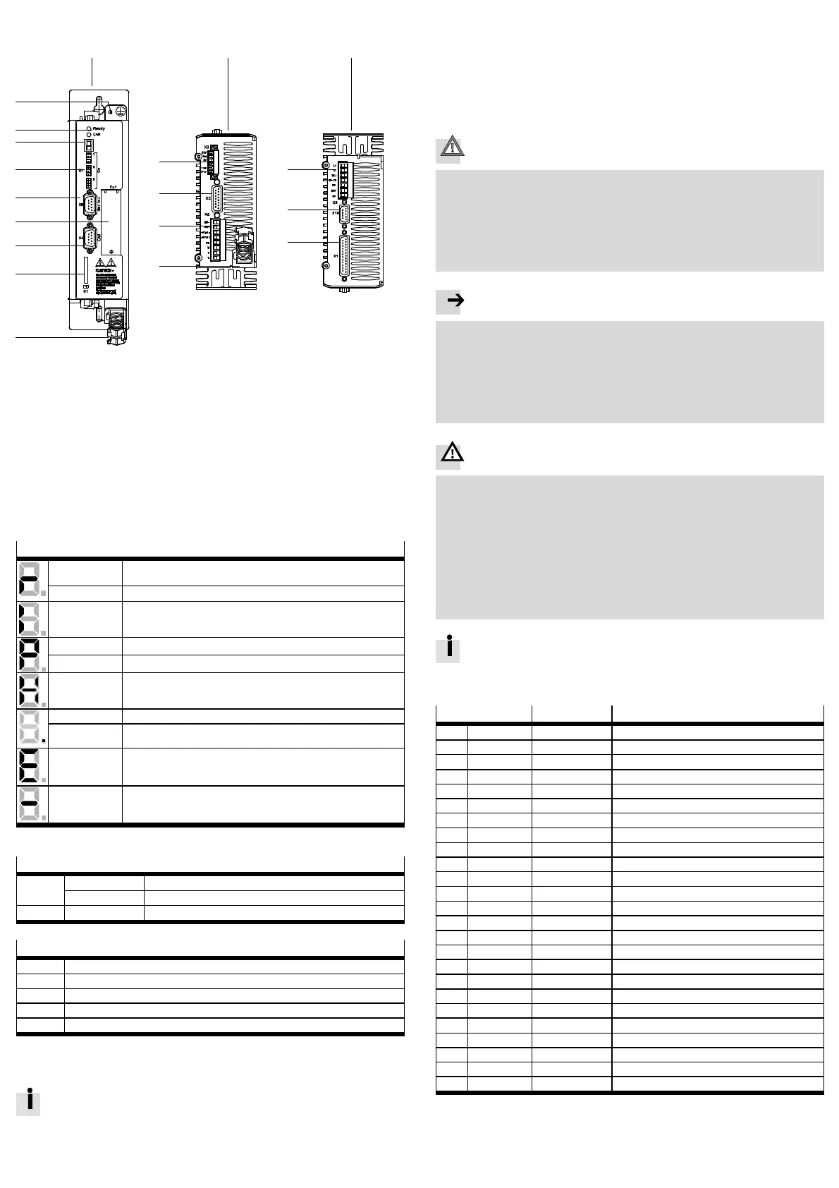
1 Front view
2 Bottom view
3 Top view
4 Earthing screw (central PE
connection)
5 LED status display
6 7-segments display
7 [S1]: DIP switch
8 [X5]: RS232/RS 485
9 [EXT]: Slot for CAMC-...
aJ [X4]: CAN bus
aA [ M1]: S D memory card
aB [ X3] STO interface
aC [ X2] Encoder
aD [ X6] Motor
aE Shield connection terminal
aF [X9] Power supply
aG [ X10] Master/Slave
aH [ X1] I/O interface
Fig. 1 Motor controller CMMS-AS-...-G2
2.2 Display and c ontrol elements
7-segments display
1)
Rotating outside
segments
Speed mode (speed adjustment):
Display changes corresponding to rotor position and speed.
Middle segment Controller enable active (motor is energised).
I Force mode (current control).
Pxxx Positioning mode, record number x x x
PHx Homing phase x
H Two-channel safety function requested (DIN4 [X1.21] and Rel [X3.2]).
Point Start program (Bootloader) active.
Flashing point – Firmware file (memory card) is being read.
– Display of errors through the start program.
Exxy Error (E = error)
Number: Two-position main index (x x), single-position subindex (y)
Example: E 0 1 0 section 7.
–xxy– Warning
Number: Two-position main index (x x), single-position subindex (y).
Example:-170- section 7.
1) Several characters are displayed one after the other.
LED display
Ready Green Operating status/controller enable
Flashing green Parameter file (memory card) is being red/written
CAN Yellow Status display: CAN bus active
DIP switch
S1.1 … 7 CAN bus address or MAC-ID
S1.8 Automatic loading of new firmware and parameter files from memory card
S1.9 … 10 Setting th e CAN-bus transmission rate
S1.11 Activatio n of th e CAN-bus interface
S1.12 Terminating resistor for CAN-bus
3 Mechanical installation
3.1 Assembly
Observe the information on the installation dimensions and free spaces in
the hardware description GDCP-CMMS-AS-G2-HW-...
For vertical mounting onto a control c abinet mounting plate:
• Mount the ac c ompanying mounting bracket to the motor controller.
• Use the motor controller exclusively in a control cabinet:
– The mounting position is vertical with the power supply lines [X9] lea ding
upwards.
– Mounting to the mounting brackets with M5 screws.
4 Electrical installation
Caution
Danger from u nexpected movement
Faulty pre-assembled lines may destroy the electronics and trigger unexpected
movements of the motor.
• When wiring the system, use only the supplied plug connectors and prefe r ably
the cables listed in the catalogue as accessories.
www.festo.com/catalogue
• Lay all flexible lines so that they are free of kinks and free of mechanical
stress; if necessary use chain link trunking.
Note
ESD (electrostatic discharge) c an cause damage to the device or other system
parts at plug connectors that are not used.
• Before installation: Earth the system par ts and use appropriate ESD equip-
ment ( e.g. shoes, earthing straps etc.).
• After installation: Seal unassigned D-sub plug connectors with protective caps
(available at authorized dealers).
• Observe the handling specifications for electrostatically sensitive devices.
Warning
Danger of electric shock
Motor controllers are devices with increased leakage current ( > 10 mA). If wiring
is incorrect or the device is defective, high voltage can occur on the housing,
which can result in serious injury or even death if the ho using is touc hed.
• Before commissioning, also for brief measuring and test purposes, connect
the PE protective c onductor:
– to the earthing screw of the c ontroller housing,
– to pin PE [X9.5], power supply. The cross section of the protective conduct-
or at PE [ X9.5] must correspond at least to the cross section of the external
conductor L [ X9.1].
• Observe the regulations of EN 50178 and I EC 60204-1.
Observe th e information on safe and EMC-suitable installation and on
protective earthing in the Hardware desc riptio n GDCP-CMMS-AS-G2-HW-...
4.1 I/O interface [X1]
Pin
Value Assignment in 0 mode – positioning
1 SGND 0V Screening for analogue signals
2 DIN12/AIN0 – Mode bit 0/setpoint input 0
2)
3 DIN 10 – Record selection bit 4 (high active)
4 +VREF +10V ±4 % Reference output for setpoint value potentiometer
5 – – –
6 GND24 – Reference potential for digital I/O modules
7 DIN 1 – Record selection bit 1 (h igh active)
8 DIN 3 – Record selection bit 3 (h igh active)
9 DIN 5 – Controller enable (high active)
10 DIN 7 – Limit switch 1
11 DIN 9 – Mode bit 1
12 DOUT1 24 V 100 mA Motion complete (high active)
1)
13 DOUT3 24 V 100 mA Common error (low active)
1)
14 AGND 0V Reference potential for analogue signals
15 DIN13/#AIN0 –/Ri = 20 kΩ Stop (low active)/reference potential AIN0
2)
16 DIN 11 – Record selection bit 5 (high active)
2)
17 AMON0 0…10V±4% Output: a nalogue monitor 0
18 +24VDC 24 V 100 mA Output: 24 V DC, lo oped through from [X9.6]
19 DIN 0 – Record selection bit 0 (high active)
20 DIN 2 – Record selection bit 2 (high active)
21 DIN 4 – Output stage enable (h igh active)
22 DIN 6 – Limit switch 0
23 DIN 8 – Start for the positioning procedure (high active)
24 DOUT0 24 V 100 mA Output: Controller ready for operation (high active)
25 DOUT2 24 V 100 mA Start acknowledged (low active)
1)
1) Default setting, configurable in the Festo Configuration Tool (FCT).
2) Pin allocation with control via analogue input

 Loading...