5 Commissioning
Note
Danger from unexpected movement of the motor or axis
• Make sure that the movement does not endanger anyone.
• Parameterise the motor c ontroller with the Festo Configuration Tool (FCT)
before enabling the controller via DIN5 [X1.9].
– Bypassing of safety equipment is impermissible
Recommendation for first commissioning without safety equipment
sec tion 4.3
Note
Damage to the motor controller
The motor controller is damaged in case of
– excessive operating voltage
– polarity reversal of the operating voltage connections
– interchange of operating voltage and motor c onnections
– short circuits in the motor circuit between the motor phases and PE
• Comply with the specified values for the supply voltage.
• Before switching on, check the connections [X9] and [ X6].
• Check that no PE short circuit is present in the motor connection circuit.
Before switc hing on the power supply:
Check installation of the motor c ontroller:
• Check all connections.
• Connect all PE protective conductors, even for brief measuring and test pur-
poses.
• Mounted module or c over plate on the c ard slot [EXT]. Mounted line o n [X9] and
[X6].
Check oper ating status
1. Make sure that the c ontroller enable is switched off (controller enable: DI N 5
[X1.9] ).
2. Switch on the power supplies of all devices. The READY LED on the front of the
device should now light up.
If the READY LED is not lit, there is a malfunc tion. If an “E” appears in the 7-seg-
ments display followed by a sequence of numbers, this is an error message and
you must eliminate the cause of the error.
Additional steps for prepara tion of commissioning can be found in the
Function de scription GDCP-CMMS-AS-G2-FW- ...
6 Obligations of the operator for the safety function
The operational capability of the safety device is to be checked at adequate inter-
vals. It is the responsibility of the operator to choose the type of c heck and time
intervals in the specified time period. The check is to be conducted so the flawless
functioning of the safety device in interaction with all the components can be veri-
fied.
Recommendation: Carry out a performance test at least every 24 hours.
7 Diagnostics and fault clearance
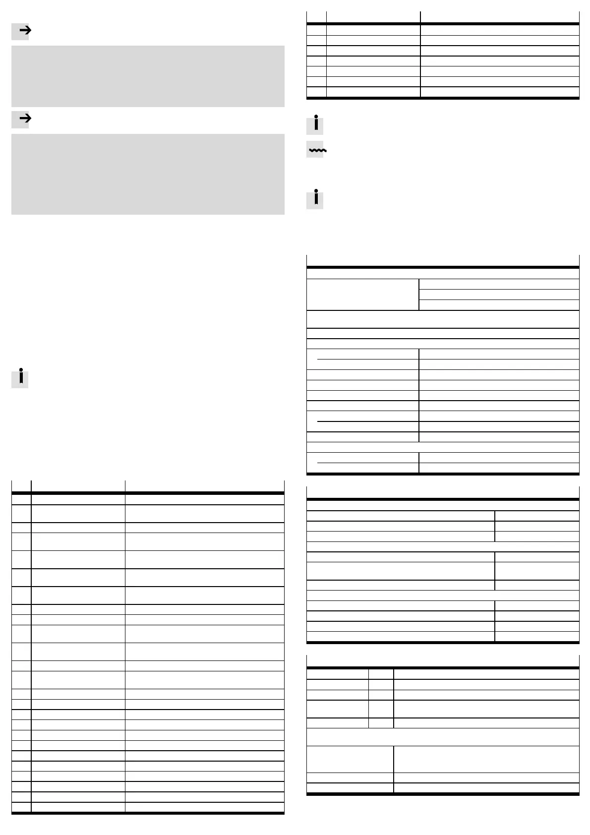
No.
Message group Cause/measure
01-x Internal error – stack overflow Load approved firmware.
02-x Undervo ltage in intermediate
circuit
Check power supply, intermediate circuit vol tage,
undervoltage monitoring (threshold value).
03-x Temperature monitoring, motor Check parameterisation (current regulator, limits).
04-x Temperature monitoring,
electronics
Check installation conditions and cylinder sizing.
05-x Internal v o ltage supply Ch eck 24 V logic supply. If error is present without
connected peripheral equipment repair.
06-x Intermediate circuit
(over-current)
Check motor, cable and motor controller.
07-x Intermediate circuit
(over v o ltage)
Check design and connection of the braking resistor.
08-x Angle encoder Ch eck encoder and encoder signals.
11-x Homing Check homing, switch arrangement.
12-x CAN Re-start CAN controller. Ch eck CAN configuration in the
controller. Check wiring.
14-x Motor identification Check intermediate circuit voltage, encoder cable.
Motor blocked, e.g. ho lding brake does not release?
16-x Initialization Load firmware again. Hardware defective ?
17-x Following error monitoring Enlarge error window. Parameterise acceleration to be
less. Moto r overloaded?
18-x Temperature monitoring Check installation conditions.
19-x I²t monitoring Motor/mechanics blocked or sluggish?
21-x Current measurement If the error occurs repeatedly hardware defective.
22-x PROFIBUS Check slave address, bus termination, cabling.
25-x Firmware Update the firmware.
26-x Data flash Load factory setting. Hardware defective?
29-x SD card Check SD card.
31-x I²t monitoring Check motor and mechanical system.
32-x Intermediate circuit Check mains v o ltage/power supply, braking resistor.
35-x Fast stop Check parameterisation.
40-x Software end po sition Check target data and positioning range.
41-x Travel program Check parameterisation.
No. Message group Cause/measure
42-x Positioning Parameterisation/sequence control, homing?
43-x Limit switch error Check parametrisation, wiring and limit switches.
45-x STO error Check acti vat ion; the error must not recur.
64-x DeviceNet error Check configuration and network.
65-x DeviceNet error Check configuration and network.
70-x Operating mode error Check factor group and impermissible change.
79-x RS232 error Check wiring and transferred data.
8 Repair and disposal
Repair or maintenance of the motor controller is not permissible. If re-
quired, re place the motor controller.
Observe the local regulations for environmentally friendly disposal of elec-
tronic components.
9Technicaldata
The complete technical data on CMMS-AS -...-G2 can be found in the
Hardware description GDCP-CMMS-AS-G2-HW-...
When using the safety function, observe the special technical data and
restrictions on environmental c onditions in dependence on required out-
put nominal power in the description STO GDCP-CMMS-AS-G2-S1-...
General technical data
Approvals
CE marking (see declaration of
conformity)
in accordance with EU Machinery Directive 2006/42/EC
in accordance with EU Low Voltage Directive
in accordance with EU EMC Directive
The device is intended for use in an industrial environment. Measures may need to be
implemented in residential areas for interference suppression.
Operating and environmental conditions
Permissible setup altitude above sea level
with nominal power [m] 1000
with power reduction [m] 1000 … 2000
Air h umidity [%] 0 … 90 (non-condensing)
Protection class IP20
Degree of contamination 2
Ambient temperature
with nominal power [°C] 0…+40
with power reduction [°C] +40 … +50
Storage temperature [°C] –25 … +70
Vibrationandshockresistance
Operation in accordance with EN 61800-5-1, section 5.2.6.4
Transport in accordance with EN 61800-2, section 4.3.3
Power supply/braking resistor [X9]
Load voltage
Input v o ltage [V AC] 95 … 250 (single-phase)
Input current [A] 4…5
Mains frequency [Hz] 50 … 60
Logic supply
Nominal voltage [V DC] 24 ± 20 %
Nominal current (outputs unloaded, with o ut ho lding
brake)
[A] 0.35
Max. current (incl. holding brake) [A] 1.7
Connection for external braking resistor
Braking resistor [Ω] ≥ 100
Pulse power (for 500 ms) [W] ≤ 1600
Nominal power [W] ≤ 100
Operating vo ltage [V] 400
Safety reference data and safety specifications
Safety function ST O Safe restart interlock (STO, Safe Torque Off)
Category 3 Grading in categories as per EN ISO 13849-1
Performance Level PL d Performance level as per EN ISO 13849-1
T [Years] 20 Proof test interval
duration of use as per EN ISO 13849-1
MTTFd [Years] 528 Mean time to dangerous failure.
Due to the service life of the internal switching relay, th e safety data for the STO function apply
for an annual actuation rate of Die nop = 500,000 / a (CMMS-AS-…G2 from Rev. 02).
Type t e st The functional safety engineering of the product has been
certified by an independent testing authority in accordance with,
see certificate www.festo.com
Certificate issuing authority MFS 09030
Reliable component Yes, for th e STO safety function

 Loading...


