Festo CP−FB13−E 0802e English14
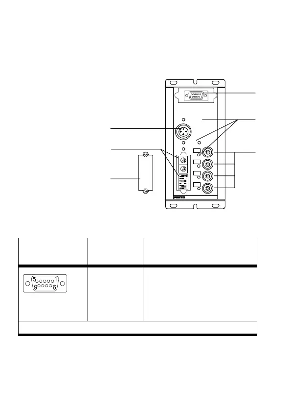
2 Connecting and display elements
1 Field bus connection
2 LEDs for bus,
voltages and
CP strings
3 CP connections
4 Switch cover
5 Rotary and
DIL switches for
configuration
6 Connection for
power supply
0
1
3
2
SAVE
POWER
24VDC
POWERV
BUSERROR
ERROR
PROFIBUS−DP
6
5
2
7
8
9
0
1
3
4
6
5
2
7
8
9
0
1
3
4
1
2
3
4
5
6
2.1 Pin assignment of the field bus connection
Sub−D−9 socket
on the node
Pin no. Designation
3. RxD/TxD−P
4. CNTR−P
5. DGND
6. VP
8. RxD/TxD−N
Receive/send data−P
Repeater control signal
Data reference potential (M5V)
Power supply voltage+ (P5V)
Receive/send data−N
Pins 1, 2, 7, 9: not connected
Detailed information can be found in the manual
P.BE−CP−FB13−E−.. .
 Loading...