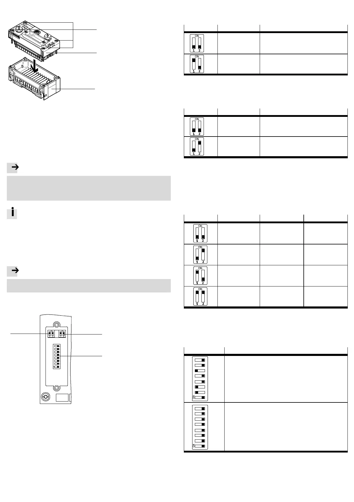
When built-in, the bus node is located in an interlinking block of the CPX terminal.
3
1
2
1 TORX T10 screws; tightening
torque 0.9 … 1.1 Nm
2 CPX bus node
3 Interlinking block with contact rails
Fig. 4
4.1 Dismantling
1. Unscrew screws using a TORX screwdriver (size T10).
2. Pull bus node off cautiously and without twisting.
4.2 Mounting
Note
Damage to the interlinking block
• Use appropriate screws, dependent on the material of the interlocking block:
– plastic interlinking block: thread-cutting screws
– metal interlinking block: screws with metric thread
Both types of screws are enclosed respectively when ordering the bus
nodeasasinglepart.
1. Check seal and seal surfaces. Replace damaged parts.
2. Push the bus node carefully and without tilting into the interlinking block up to
the stop.
3. Turn the screws into the existing thread.
4. T ighten the screws in diagonall y opposite sequence. Tightening
torque: 0.9 … 1.1 Nm.
Note
• Use cover c aps to seal unused connections. In this way, protection class
I P65/IP 67 is assured.
5 Setting the DIL switches
1
2
3
1 DIL switch 1: Operating mode, EtherCAT interface
2 DIL switch 2: Diagnostics mode, data field size, bootloader
3 DIL switch 3: EtherCAT address
Fig. 5
5.1 Removal of the DIL switch cover
To set the DIL switches, you must remove the cover:
1. Switch supply power off.
2. Unscrew the two mounting screws of the transparent c over and remove the
cover.
5.2 Setting the operating mode with DIL switch 1
You can set the operating mode of the bus node with switch element 1.1 of DIL
switch 1.
DIL switch 1
Setting Operating mode
DIL 1.1: OFF
(Factory setting)
Remote I/O
All functions of the CPX terminal are controlled
directly by the EtherCAT I/O controller o r
a higher-level PLC.
DIL 1.1: ON R emote controller
A CPX-FEC o r CPX-CEC integrated into the terminal
controls all functions
Fig. 6
5.3 Setting the EtherCAT interface with DIL switch 1
You set the EtherCAT interface of the bus node with switch element DI L 1.2 of DIL
switch 1.
DIL switch 1
Setting Function
DIL 1.2: OFF
(Factory setting)
Modular device profile (MDP)
DIL 1.2: ON Fixes I/O size (64 byte I/A),
compatible with the bus node CPX-FB38
Fig. 7
5.4 Setting the diagnostics mode, I/O bytes or starting of the bootloader with
DIL switch 2
The function of DIL switch 2 is dependent on the set operating mode of the CPX
terminal:
– setting of the diagnostics mode in Remote I/O operating mode
– setting the data field size in the remote controller operating mode
– starting the bootloader in both operating modes.
DIL switch 2
Setting Remote I/O Remote controller
DIL 2.1: OFF
DIL 2.2: OFF
(Factory setting)
I/O diagnostics inter-
face and status bits
switched off
8byteI/8byteOfor
communication of the
bus node with th e
CPX-FEC or CPX-CEC
DIL 2.1: OFF
DIL 2.2: ON
Status bits are
switched on
+ 16 I bits (only 8 bits
used)
Reserved
DIL 2.1: ON
DIL 2.2: OFF
I/O diagnostics inter-
face is switched on
+16I/Obits
16 byte I/16 byte O for
communication of the
bus node with th e
CPX-FEC or CPX-CEC
DIL 2.1: ON
DIL 2.2: ON
Bootloader
(Restore the firmware in
case of loss of function)
Bootloader
(Restore the firmware in
case of loss of function)
Fig. 8
5.5 Setting the EtherCAT address with DIL switch 3
Assign a free EtherCAT address (device identification value) to the bus node with
the switch elements DIL 3.1 … 3.8. Setting an EtherCAT address is optional ( e.g. for
the Hot Connect function).
DIL switch 3
Function
12 34 56 7
8
2
0
2
1
2
2
2
3
2
4
2
5
2
6
2
7
Binary-coded input o f th e Eth erCAT address
1)
Example on left in figure:
EtherCAT address
=2
1
+2
2
+2
5
=2+4+32=38
12 34 56 7
8
2
0
2
1
2
2
2
3
2
4
2
5
2
6
2
7
Binary-coded input o f th e Eth erCAT address
Example on left in figure (all switch elements are OFF):
EtherCAT address = 0, the programmed Eth erCAT address in the E EPROM
is used (factory setting).
1) Possible EtherCAT addresses are 1 to 255.
Fig. 9

 Loading...