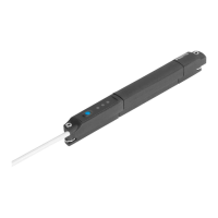
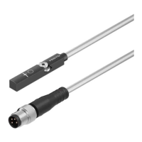
SDAT-MHS
20 Festo – SDAT-MHS – 2017-11f English
6 Operation
6.1 Magnetic direction detection and correction
At initial start-up or after a reset to factory settings, the position sensor emits signals directly using the
currently detected magnetic direction.
The magnetic direction detection and, with it, the signal curve are corrected during ongoing operation
when the following cases occur:
– The position sensor was placed in operation in a position where a correct magnetic direction detec
tion was not possible (e.g. due to ferromagnetic materials near the sensor or within the drive or
gripper).
– The position sensor was turned 180° in the slot after the magnetic direction was recognised as
stable.
Note
Brief incorrect signals at the sensor output can occur if automatic correction of the
magnetic direction detection is required è Chapter 8.2.
6.2 LED indicators
Status signals in normal operation
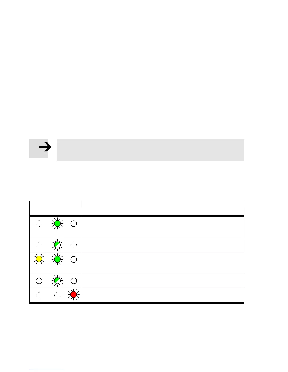
LED indicator Description
Yellow Green Red
Green LED illuminated: Ready status (yellow: Any, red: Off ).
– Analogue output function or switching output operating mode.
– Piston within the sensing range.
Green LED flashing at 1 Hz: Ready status.
– IO-Link operating mode.
Yellow and green LEDs illuminated: Ready status.
– Switching output switched.
– Piston in the range of a programmed function.
Green LED flashing 3 seconds at 3 Hz while the operating key is pressed:
Operating key blocked.
Red LED illuminated: Status display.
– Piston outside the sensing range.
Tab. 4 LED displays in normal operation


 To Next Page