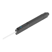
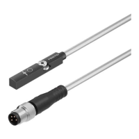
SDAT-MHS
Festo – SDAT-MHS – 2017-11f English 31
11 Appendix
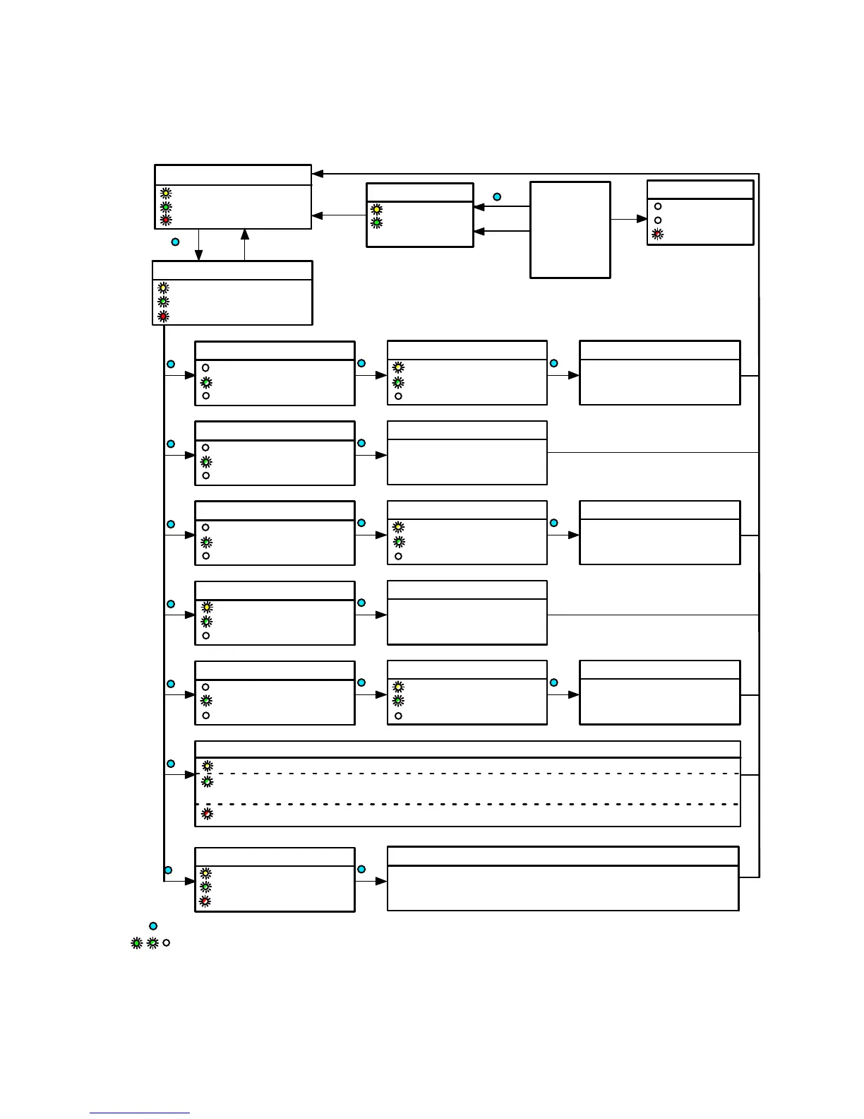
SIO operation
Switching output status
ON
ON, if OoR
3 x
Key combination
invalid
Set-up mode
Yellow +
Green flash simultaneously
ON, if OoR
Window comparator
Yellow OFF
1 x flash briefly / 2 s
Red OFF, if in range
1)
1 x
Teach point 1
Flashes
1 x flash briefly / 2 s
Red OFF, if in range
1)
1 x
Teach point 2
1 x
Cylinder switch function
Yellow OFF
2 x flash briefly / 2 s
Red OFF, if in range
1)
2 x
Teach point
1 x
Hysterisis comparator
Yellow OFF
3 x flash briefly / 2 s
Red OFF, if in range
1)
3 x
Teach point 1
Flashes
3 x flash briefly / 2 s
Red OFF, if in range
1)
1 x
Teach point 2
1 x
Switching logic NO/NC
ON if NO / OFF if NC
4 x flash briefly / 2 s
Red OFF, if in range
1)
4 x
Inverting NO or NC
1 x
Scale
Yellow OFF
5 x flash briefly / 2 s
Red OFF, if in range
1)
5 x
Teach point 1 (4 mA)
Flashes
5 x flash briefly / 2 s
Red OFF, if in range
1)
1 x
Teach point 2 (20 mA)
1 x
Display configuration: Cyclical flash signals in the sequence green - yellow - red
6 x
Switching logic: 1 x - normally closed (NC), 2 x - normally open (NO)
Function: 0 x - deactivated, 1 x - window comparator, 2 x - cylinder switch function,
3 x - hysteresis comparator
Scaling: 1 x - user-configured, 2 x - total sensing range
Reset
Yellow + green + red flash
simultaneously at 1 Hz
10 x
Factory setting
Switching function: None
Switching logic: Normally open (NO)
Scaling: Total sensing range
1 x
Abort
Yellow +
Green ON for
0.5 s
Errors
Yellow OFF
Green OFF
Red flash 3 Hz
3 s
t > 60 s
From each
status in the
diagram
1 x = Press operating key (e.g.: 1 x)
= LED illuminated / LED flashing / LED OFF (e.g.: Green LED)
1) Teaching of a position out-of-range (OoR) causes the red LED to flash until the magnet is back in the sensing range (in range).
Fig. 13 Settings via the operating key and LED indicators (not IO-Link operation)


 To Next Page