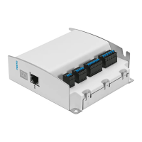
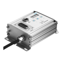
Do you have a question about the Festo SEC-AC-305 and is the answer not in the manual?
Details on correctly installing and fitting the drive, including checks for secure mounting and sufficient workspace.
Procedure for verifying the device is ready for operation, including checks for the controller enable switch and status LEDs.
Information about the contents of the CD-ROM accompanying the parametrizing software, including device and parametrizing files.
Specifies the necessary PC hardware and software prerequisites for installing and running the parametrizing program.
Explains how to navigate and use the parametrizing program interface, focusing on standard buttons and numerical entry fields.
Step-by-step guide for installing the parametrizing software on the PC, including running the setup executable.
Describes how to establish serial communication between the PC and the servo controller, covering interface and baud rate settings.
Troubleshooting guide for resolving issues when the parametrizing program cannot open the serial interface port.
Provides a table of common serial communication faults and their corresponding remedies for successful connection.
Explains how to select different user modes (Beginner, Advanced, Expert) to control access to program functions.
Details the procedure for transferring pre-tested parameter sets from a CD to the servo controller for specific motors or applications.
Instructions for setting the permitted current limits for the motor, referring to manufacturer data sheets for correct values.
Configuration of the logic that determines when the controller can be enabled, typically via digital input for initial commissioning.
Describes the automatic identification process for determining motor parameters like pole pairs and offset angle.
Explains how to set the amplification factor and time constant for the current controller, often using automatic identification.
Assigning sensible basic values to the speed controller, with actual optimization performed later in the commissioning process.
Overview of the SEC-AC's motor control modes: speed, position, and torque control, selectable via the commands window.
Configuration of setpoint selectors to choose between different input sources like RS232 or analog inputs for speed or torque control.
Setting up the PC screen display to show measured values like motor speed and current during operation.
Procedure for testing the controller enable function, ensuring the motor operates correctly and safely after initial setup.
Configuring a filter to smooth the actual measured speed value, improving control behavior and stability.
Methods for tuning the speed controller parameters using the oscilloscope function to achieve optimal performance with minimal overshoot.
Steps for tuning the positioning module parameters, ensuring accurate and efficient movement of the drive system.
Explains the management of parameter sets, including reading, saving, and resetting parameters for reliable motor operation.
Instructions for externally saving and managing parameter sets on hard disks or diskettes using WPA files.
Describes how to access and modify parameter sets without a direct serial connection to the servo controller.
Explains the importance of correct offset angle and pole pair settings for faultless drive operation and phase current commutation.
Details how the SEC-AC automatically determines motor parameters like pole pairs, phase sequence, and resolver offset angle.
Discusses the role of the current controller in specifying motor current and how amplification factor and time constant affect its performance.
Provides a block diagram illustrating the basic control structure of the SEC-AC, including cascade control loops.
Details how to configure the system for torque-control mode, where the motor maintains a specified torque.
Explains the configuration for speed-control mode, where the SEC-AC attempts to maintain a specified motor speed.
Configuration steps for positioning tasks, including setting destinations, reference travel, and movement profiles.
Describes how to couple two servo controllers for master-slave operation, enabling synchronized movements like speed-synchronous positioning.
Details the timing relationships for digital inputs and outputs, crucial for controlling motor enable and limit switch functions.
Accessing the 'Expert' mode to send commands directly to the servo controller and observe replies for debugging.
Incorporating additional information, such as motor selection lists or special parametrizings, into the program.
Methods for safely closing and exiting the parametrizing program, including menu options and key combinations.
Specifying setpoints (speeds or torques) via RS232 or other input methods, including the transfer of setpoint values.
Configuring the analogue outputs to display control variables like motor speed or current, usable with oscilloscopes or processing signals.
Assigning input voltages to setpoints (speed or torque) and defining the conversion factor and zero point reference.
Processing setpoint jumps by calculating a ramp function with an adjustable gradient for smoother transitions.
Configuring speed monitoring to trigger a message when the motor speed falls within a defined range or hysteresis.
Configuring digital outputs to transmit various status messages from the controller, such as position reached or fault conditions.
Monitoring and setting thresholds for the intermediate circuit voltage to prevent faults or controller switch-off.
Activating and configuring the automatic brake function for motors equipped with a parking brake.
Understanding the error window's function, how faults are displayed, and the steps for fault analysis and remedy.
Setting the display language of the parametrizing program to German or English.
References the setting of user modes as described in Chapter 4 for controlling access to program features.
Accessing a window to observe serial interface communication, primarily for debugging purposes.
Information on setting torque control mode, found in Chapter 8, for specifying motor torque.
Utilizing the oscilloscope function to represent signal curves and optimize controller and positioning module performance.
Explanation of the status messages displayed by the SEC-AC, indicating controller states like enable or motor operation.
Overview of the servo controller's extensive monitoring functions and its ability to recognize hardware and control circuit faults.
How the user is informed of faults via the 7-segment display, error window, and status bar, including error code interpretation.
A comprehensive table listing fault codes, their meanings, and recommended measures for rectifying the faults.
Alert regarding potential compatibility issues when using older firmware versions with the parametrizing program.
Guidelines for using RS232 commands for direct access to controller variables, emphasizing caution for experienced users.
A reference table of general commands, their syntax, and expected replies for controlling the SEC-AC via RS232.
RS232 commands for switching between operating modes like torque control, positioning, and synchronization.
RS232 commands for setting the motor speed and reading actual speed values, both filtered and unfiltered.
RS232 commands for executing reference travel and controlling motor positioning, including command abbreviations.
Commands for reading and setting the status of the synchronization unit, though full control may require dealer assistance.
RS232 commands for activating, deactivating, and managing the parking brake function of the motor.
RS232 commands used by the parametrizing software for initial setup and calibration of the servo controller.
Commands for reading and writing controller parameters, providing direct access to internal variables.
Practical examples of RS232 commands used to set operating modes, control positioning, and configure parameters.
| Number of digital inputs | 4 |
|---|---|
| Number of digital outputs | 4 |
| Short circuit strength | Yes |
| Max. output current | 0.5 A |
| Nominal output voltage DC | 24 V |


