The Festo Didactic TP 1410 Servo Brake and Drive System, also referred to as a motor test bench, is a comprehensive load and drive system designed for analyzing test objects under various load conditions. Its design emphasizes a clear distinction between the test object and the load, facilitating quick setup and exchange of test objects (motors) through a practical quick-change system. Test objects are connected via the versatile A4 EduTrainer®, which allows for flexible use.
Function Description:
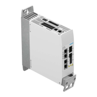
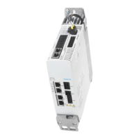
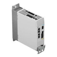
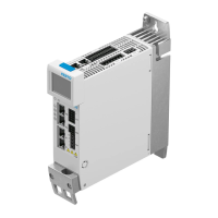
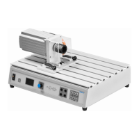
The core of the system is the test bench housing, which serves as a mounting surface for the servo motor and the test object. It also acts as a protective enclosure for the integrated controller and power pack. The front panel of the housing incorporates control, display, and connector panels.
The servo brake motor, a key component, functions either as a brake or a drive unit, depending on the control input. The current for its operation is regulated by the integrated controller. This controller manages the energy supply to the servo brake motor and can be operated either via a rotary control knob on the device or externally through a USB interface connected to a PC running Windows and Festo Didactic's DriveLab software.
The USB port serves as the interface for connecting the test bench to a PC, significantly expanding its functionalities. With DriveLab software, users can automatically record characteristic curves, configure static loads, and simulate various load models.
The connector panel provides terminal sockets for supplying power to the test object (L1, L2, L3), a temperature input, and an error output. The rotary control knob acts as both a regulator and a switch for operating the test bench, while the integrated display shows measured values, characteristic values, and the current operating mode.
Operating Modes:
The test bench offers three primary operating modes:
- Torque Control (Torque Specification): In this mode, the objective is to record a characteristic curve for motor speed in rpm. The test object is subjected to a constant, preselected torque value across its entire speed range.
- Speed Control (Speed Specification): This mode aims to record a characteristic curve for torque at one or more preselected motor speeds.
- PC Mode: When activated, the test bench is controlled remotely from a PC via the DriveLab software.
Usage Features:
The system is designed for ease of use in teaching and training applications. Simple experiments, such as recording characteristic curves, can be performed without a PC or software, with the integrated display providing all necessary information.
Mounting a test object involves a straightforward process:
- Ensure the mains switch and power switch are off.
- Release both quick clamp levers (A) on the test bench by setting them to the vertical position.
- Press and hold the two clamp levers (B) on the test object.
- Guide the test object's receiving plate into the slots on the test bench housing.
- Push the test object towards the servo brake motor until the limit switch (C) is actuated.
- Securely clamp the test object by releasing the clamp levers (B) and then rotating the quick clamp levers (A).
Connecting the test object requires adherence to safety protocols:
- Turn off the mains switch and power switch.
- Connect cables according to the provided wiring diagram.
- Connect the motor's thermo-switch terminals to the test bench.
- Re-enable supply power before starting measurements.
Maintenance Features:
The manual emphasizes safety precautions to prevent disturbances and enhance system safety. Regular checks for safety-conscious work habits are recommended for personnel.
Troubleshooting is addressed with a table of common error messages, their causes, and remedies:
- Flange error: Indicates the test object is not mounted in the correct position. Remedy: Reposition the test object correctly.
- Temp error: Can mean the thermo-switch is not connected or the test object is overheating. Remedy: Connect the thermo-switch or allow the test object to cool down.
- Servo error: Points to a communications or control error. Remedy: Switch the test bench off and then back on again.
Important Technical Specifications:
- Dimensions: 510 mm x 380 mm x 270 mm
- Weight: 21 kg
- Ambient conditions: 0 °C to 40 °C, up to 65% relative humidity, no condensation
- Protection: IP 20
- Noise level: 70 dB
- Speed: Max. 4000 rpm
- Torque: Max. 4 Nm
- Braking power: Max. 400 W
- Duty cycle: Max. 30%
- Supply voltage: 110-230 V AC ± 10%
- Current: Max. 6 A
- Connector panel for test object: L1/L2/L3, 400 V AC / 5 A
- Voltage measurement: L1/L3; L1/N; DC+/DC-, 400 V AC or 250 V DC
- Current measurement: L1/DC+ input → L1/DC+ output 5 A AC / 8 A DC
- Error switching output: 30 V / 1 A
- Thermo-switch input: 24 V DC / 0.1 A
- USB port: USB 2.0
- Control circuit: Black sockets, 24 V DC
- Primary circuit: Grey sockets, 400 V AC or 250 V DC
Safety Precautions:
- Only trained personnel familiar with safety regulations should operate the system.
- The test bench must only be used for its intended purpose in teaching and training.
- It must be in flawless safety condition.
- Never operate the test bench with the safety guard removed.
- Deactivate the rotary control knob before any manual intervention.
- The test bench requires an additional protective earth conductor for operation.
- Always turn off and secure the power switch before connecting/unplugging cables, changing setup, or cleaning.
- Use only connecting cables with safety plugs and undamaged insulation.
- Avoid abrupt changes to motor speed or torque and ensure correct motor selection to prevent mechanical or electrical damage.
- Be aware of hot housing components during operation, especially at low speeds under high load. Run motors at maximum permissible load for short periods only.
- Always connect the motor's thermo-switch to the designated input.
- Ensure cooling slots are not covered and the base plate has adequate clearance from the tabletop.
- Wear safety shoes when transporting the heavy and angular motors and test bench to prevent injury from falling objects.
- Do not use water for cleaning.