• Note the warnings and instructions on the product and in the relevant operating
instructions.
• Ensure t hat there is a supply of correctly prepared compressed air ( Technical
data).
• Pressurise your entire system slowly. There will t hen be no uncontrolled move-
ments.
5 Installation
5.1 Mechanical
Note
• Installation and c ommissioning may only be performed in acc ordance with the
operat ing instructions and by qualified personnel.
• Handle the VPPM-...C1 with care so that the electrical c onnection is not dam-
aged. This could lead to an impairment of function.
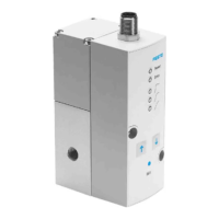
• Make sure there is sufficient space for the cable
connection and tube couplings. In this way you will
prevent the c onnecting cable from being bent.
• Place the VPPM-...C1 as near as possible to the
consuming device. This leads to improved control
precision and shorter response times.
Fig. 6
Wall mounting (in-line valve)
• Fasten the VPPM-...C1 (1/8” and 1/4”) in the inten-
ded position with two M4 screws. In order to do
this use bracket type VAME-P1-A (see diagram).
When mounting the VPPM with the aid of the brack-
et, the VPPM-...C1 may only be loaded statically
(torque: approx. 1.5Nm).
• Fasten the VPPM-…C1 (1/2”) with two M5 screws in
the intended position (torque 2.0Nm).
Fig. 7
H-rail mounting (in-line valve)
• Mount the H-rail adaptor on the VPPM-...C1 using the screws included (x”: M4
x 65, ¼”: M4 x 77) (torque approx. 1.5Nm).
• Hang the VPPM-... onto the H-rail.
• Secure the VPPM...C1 with the retaining screws of the H-rail adapter ( torque
1.5Nm).
1
2
3
4
5
1 H-rail adapter
type VAME-P1-T
2 VPPM-...C1
3 Mounting screws M4
4 H-rail
5 H-rail clamping unit
Fig. 8
Sub-base mounting (flanged valve)
• Fasten the VPPM-...C1 2 on the pneumatic mani-
fold rail type VABM-P1-SF-G18-...1.
• Tighten the fastening screws 3 (torque 1.5 Nm).
Fig. 9
1
2
3
5.2 Pneumatic (in-line valve)
• Remove the sealing elements from the compressed air ports.
• Attach the pneumatic tubing to the following connections ( Fig. 1):
– Supply port (1) Item. 5
– Supply port (2) Item. 2
• Install a silencer at the exhaust por t (3) item 3 or remove the exhaust with
ducted tubing.
Operating medium
Note
Too much residual oil content in th e compressed air will reduc e the service life of
the valve.
• When using bio-oils (oils that are based on synthetic ester or native ester, e.g.
rapeseed oil methyl ester), the maximum residual oil content of 0.1 mg/m³
should not be exceeded
( ISO 8573-1:2010 [7:4:2]).
5.3 Electric
Warning
For electrical isolation of operating voltage:
• Only use PELV circuits as per IEC/EN 60204-1 (protective extra-low voltage,
PELV) for the electrical power supply.
Also observe the general requirements for PELV circuits in accordance with
IEC/EN 60204-1.
• Use only power sources which guarantee reliable electrical isolation of the
operating voltage as per IEC/EN 60204-1.
Protection against electric shock (protection against direct and indirect contact) is
guaranteed in accordance with IEC/EN 60204-1 by using PE LV c ircuits (electrical
equipment of machines, general requirements).
Note
Long signal lines reduce the resistance to interference.
• Make sure that the signal cables are not longer than 10 m.
•
Check by means of the type plate to ascertain which valve variant you
have:
Designationontheratingplate
VPPM-...-V1...C1 VPPM-...-A4...C1
Designation Voltage variant Current variant
Electrical setpoint
value
DC 0 ... 10 V 4 ... 20 mA
Fig. 10
• Check whether the following options are required on the VPPM-...C1:
– measuring the actual voltage/current value
• Make sure that the cables are not squashed, bent or stretched.
• Use the pre-assembled cable with socket from Fe sto (Accessories
www.festo.com/catalogue). You can then guarantee that the specified protec-
tion class IP 65 and EMC are fulfilled.
• If a screened cable is used, earth t he screening on the opposite end of the cable
from the VPPM-...C1.
Note
If the Y-connecting cable type NEBV-M12G8-KD-..-M12G5 is connected to CPX
I/O modules, the I/O modules will no longer be galvanically isolated.
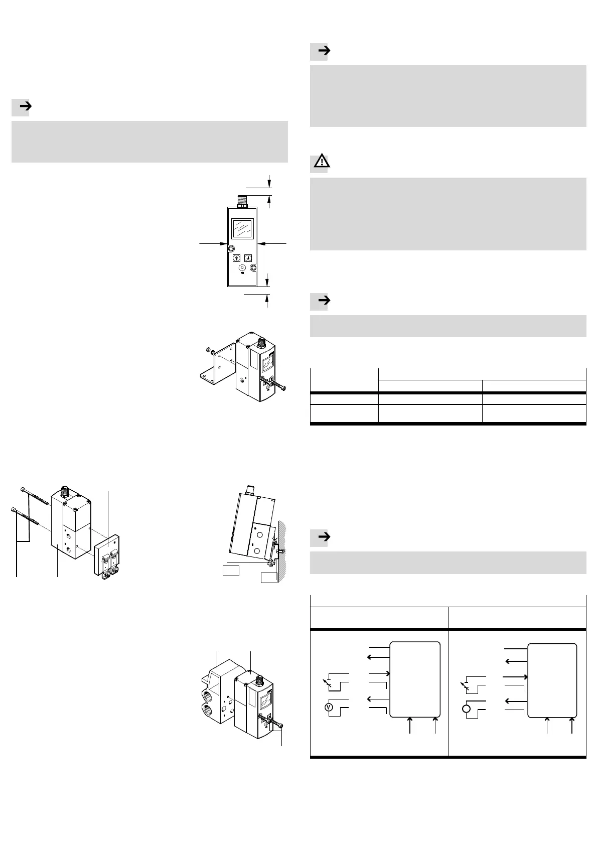
• Connect the cables of the VPPM-...C1 in accordance with the circuit diagram.
Circuit diagrams for the VPPM-...C1
Voltage variants
(type VPPM-...-V1...C1)
Current variant
(type VPPM-...-A4...C1)
W-
8
4
3
D1
ext in
D2
ext in
1
5
7
X
GND
6
W+
D3
out
U
v
0 ...10
V
2
PIN
A
7
8
4
3
D1
ext in
D2
ext in
1
5
X
GND
6
w-
D3
out
U
v
4 ...20 mA
PIN
w+
2
Fig. 11
• The individual pins on the electrical connection are assigned as follows:
 Loading...