PIN Cable
colour
1)
Port designations Plug M12
Voltage variants
type
VPPM-...-V1...C1
Current variants
type
VPPM-...-A4...C1
1 White
(WH)
Digita l input D1
1
3
2
45 6
7
8
2 Brown
(BN)
+24 V DC power supply
3 Green
(GN)
Analogue input W- (- setpoint value)
4 Yellow
(YE)
Analogue input W+
(+ setpoint value)
0 ... 10 V
Analogue input W+
(+ setpoint value)
4 ... 20 mA
5 Grey (GY) Digi tal input D2
6 Pink (PK) Analogue output X (actual value)
7 Blue (BU) G ND Supply ear th
8 Red (RD) Digital o utput D3
2)
PE braided screen on th read
1) Using the connector socket with cable as per “Accessories”. The max. tightening torque is 0.5Nm.
Fig. 12
VPPM-... circuit diagrams Switching output
PNP NPN
8
7
2
PNP
P
BN
RD
BU
0V
+24 V
R
L
RD
R
L
2
8
7
NPN
P
BN
BU
0V
+24 V
Fig. 13
6 Commissioning
6.1 Fast commissioning with factory setting
The VPPM-...C1 is delivered with the following factory setting:
• Switching behaviour: value comparator setting
• Switching point 40% FS (full scale)
The switching point is only active when a comparator is selected (threshold
value or window comparator).
• Hysteresis: 0.5 % FS
• Switching characteristic: NO ( normally open c ontact)
If you wish to use the factory setting but define a different switching point for Out,
proceed as follows;
Note
When the operating voltage is switched on, the VPPM-...C1 will automatically be
in the RUN mode ( basic setting). If you are not sure whether the VPPM-...C1 is in
the RUN mode, hold the EDIT button down for 3 s. The VPPM-...C1 will then be in
the RUN mode. You can set switching points manually.
You can set a switching point manually as follows:
1. In order to activate the EDIT mode, press the EDIT button. [Out] flashes.
2. Press the ED IT button twice. SP flashes.
3. Edit the threshold value shown with the UP or DOWN button.
4. Hold the EDIT button pressed down for 3 s. The VPPM-...C1 will then be in the
RUN mode.
6.2 Preparing for commissioning
Note
• Make sure that the VPPM-...C1 is not subjected to high-frequency irradiation
(e.g. by radio sets, mobile telephones or other devices which emit interfer-
ence). In this way you will avoid increased tolerances in the output pressure
(EMC specifications Technical data).
• The VPPM-...C1 interprets setpoint value signals which are smaller than 1%
full scale as 0V ( Output pressure range table). In this case the working
pressure will be set to the ambient pressure.
During the initial start-up the RUN mode will appear. This shows the c urrent
measured value. By briefly pressing the DOWN button you can display the setpoint
value.
The RUN mode can be accessed from ot her modes:
– Press the EDIT button down for 3 s.
– after expiration of a monitoring time (Timeout “Menu structure” section)
Proceed with preparation for c ommissioning as follows:
• Switch on the operating voltage. The VPPM-...C1 will then be in the RUN mode.
• Check the functioning of the VPPM-...C1
Observe the following points for setting the control c haracteristics via digital in-
puts or display:
Note
Selection of the control characteristics via digital inputs D1 and D2 takes priority
over the fac tory parameter sets in VPPM-...C1.
• If you wish to select the control characteristics via the factory parameters,
make sure that a logic 0 signal is present at digital inputs D1 and D2.
• You can select the desired fac tory parameter set in the EDIT menu on the
VPPM-...C1 ( Fig. 25). Parameter set Set2 (universal control characteristics)
is preselected at the factory.
• If you wish to preselect the control characteristics via the digital inputs, activate
the following signals at digital inputs D1 and D2:
Parameter set
Control characteristics Input D1
PIN 1
1)
Input D2
PIN 5
1)
1 Fast control reaction 1 0
2 Universal control reaction
(factory setting)
0 1
3 Precise control reaction 1 1
... Select parameter set via display of the
VPPM-...C1
0 0
1) 1 = 24V DC / 0 = 0V DC
Fig. 14
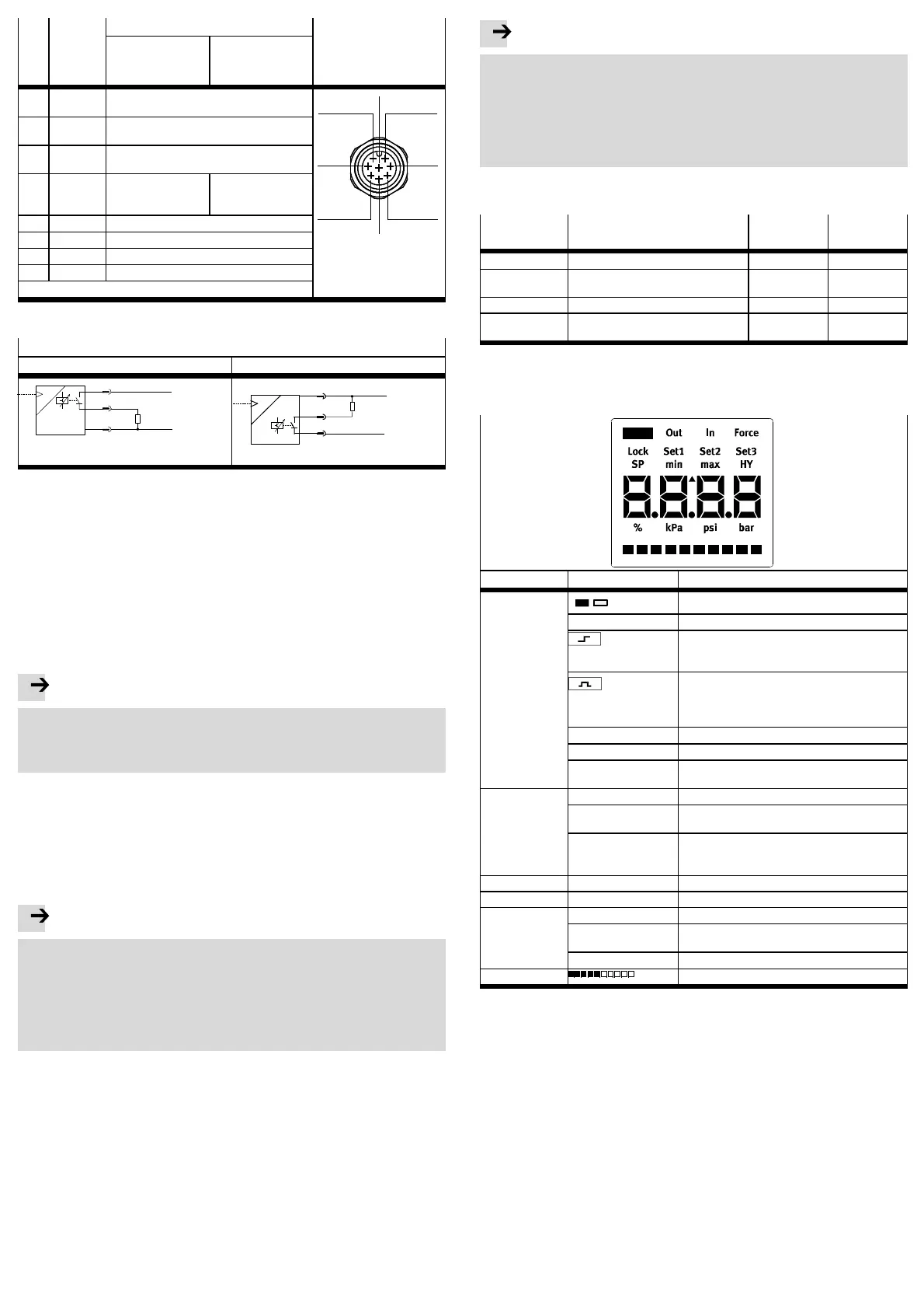
6.3 Symbols on the display of the VPPM-...C1
Menu level Symbol Description
Out
/
Switching output set/not set
[Out] Switching output
[SP]
Threshold value comparator
Switching point
[SP max]
[SP min]
Window comparator
Upper switching point
Lower switching point
SP.O. SetPoint OK
[HY] Hysteresis
[NO]
[NC]
Contact (normally open)
Contact (normally closed)
In [In] Input
[min]
[max]
Lower pressure value
Upper pressure valu e
[mA] or [V]
1)
,
[%],
[bar], [psi], [kPa]
2)
Units of the input
Force [Force] Manual setpoint specification
Set... [Set 1], [Set 2], [Set 3] Factory parameter sets
SPEC [SPEC] Special menu
[LOCK] Security code active (blocked against unautho-
rised programming)
[kPa], [psi], [bar] Units of pressure, can be switched
Pressure display as bar chart
1) Depends on the variant of the VPPM-...C1
2) Depends on unit set in SPEC menu
Fig. 15
 Loading...