Poportional pressure regulator
VPP M-...C1 (LCD)
Festo AG & Co. KG
Postfach
D-73726 Esslingen
+49 711 347 0
www.festo.com
Operating instructions 754538
1204d
Original: de
Poportional pressu r e regulator VPPM-...C1 (LCD) english....................
Note
Installation and commissioning may only be performed in accordance with these
operating instructions by technicians with appropriate qualifications.
1 Product description
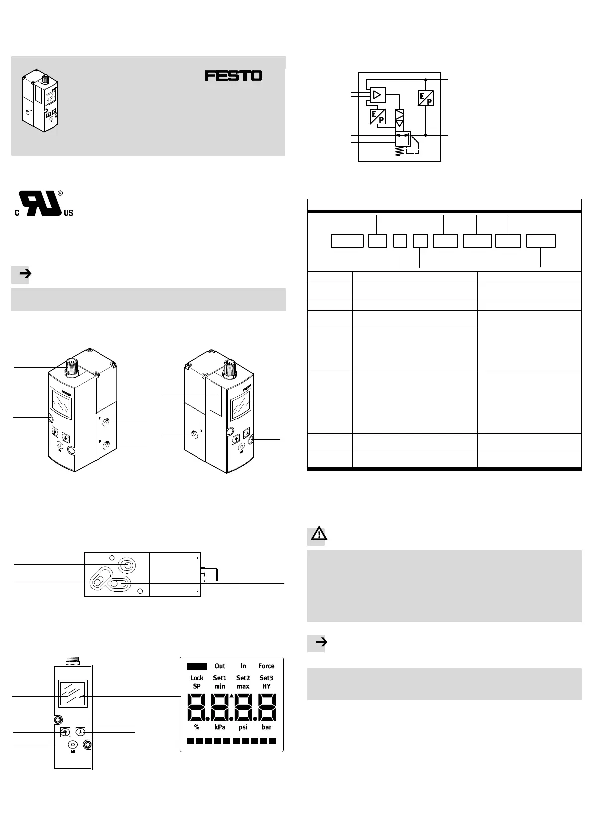
1.1 Connections, mounting holes and control sections ( in-line valve)
1
4
5
4
2
3
6
1 Electrical connecting plug M12
(8-pin)
2 Air connection (2), pressure output
3 Exhaust connection ( 3)
4 Through-holes for fastening
5 Compressed air connection (1),
supply port
6 Rating plate
Fig. 1
1.2 Pneumatic connections (flanged valve)
1
2
3
1 Duct (2) air, pressure output
2 Duct (1) compressed air , supply port
3 Duct ( 3) exhaust
Fig. 2
1.3 Display and control elements, display symbols
1
2
3
4
1 Display
2 DOWN button
3 EDIT button
4 UP button
Fig. 3
2 Application and function
The VPPM-...C1 has been designed for regulating a pressure propor tional to a
specified setpoint value. A built-in pressure sensor rec ords the pressure at the
working line and compares this v alue with the setpoint value. If the actual value
differs from the setpoint value, the regulating valve is actuated further until the
output pressure reaches the setpoint value.
+W
-W
3
1
2
X
Supply port
Setpoint value
Setpoint value
Pressure o utput
Exhaust
Pin 6
Fig. 4
3 Variants of the VPPM-...
Type code of the VPPM-...
VPPM
-
6L
-
L
-
1
-
G18
-
0L6H
--
V1N S1C1
1
4
56
2
37
Item Properties Meaning
1 Nominal size [mm]
Valve type
6, 8, 12
F (flanged), L (in-line)
2 Dynamic response class L(Low)
3 Valve function 1 (3-way p ressure regulato r
normally closed)
4 Pneumatic connection
– Flange/sub-base
– ISO thread
– NPT thread
F
G18 (1/8”), G14 (1/4”), G12 /1/2”)
N18 (NPT 1/8), N14 (NPT 1/4),
N12 (NPT 1/2)
5 Standard control range:
– Lower pressure value
– Upper pressure value
Alternative control ranges:
1)
– Lower pressure value
– Upper pressure value
0L (0 bar)
2H (2 bar), 6H (6 bar), 10H (10 bar)
...L (... = value between 0.1...10
bar) e.g. 4L
...H (... = value between 0.1...10
bar) e.g. 9H
6 – Setpoint specification
– Switching output
O4 (4 ... 20 mA),V1 (0 ... 10V)
P (PNP), N (NPN)
7 Accuracy
Operator unit
... (2 %, standard), S1 (1 %)
... (LED), C1 (LCD)
1) When an upper and lower pressure value are used, it is not possible to guarantee the overall accuracy
of the VPPM-...C1.
Fig. 5
4 Requirements for product use
Warning
Depending on the functions of the machine/system, the manipulation of signal
states can cause serious injury to human beings and damage to pro perty.
• Note that if the switching behaviour of the switching outputs is modified in
the EDIT mode, the new status will be effective immediately.
• Activate the password protection (security code) in order to prevent uninten-
tional modification by unauthorised third parties ( section 6 under EDIT
mode).
Note
Improper handling can result in malfunctions.
• Make sure that the following specifications are always observed in order to
ensure correct a nd safe use of the product.
• Compare the limit values in these operating instructions with those of your ap-
plication (e.g. operating medium, pressures, forces, torques, temperatures,
masses, speeds, voltages).
• Take into consideration the ambient conditions at the location of use.
• Comply with the regulations of the trade association, the German Technical
Control Board (TÜV), of the VDE or relevant national regulations.
• Remove all transport packing such as protective wax, foils (polyamide), caps
(polyethylene), cardboard boxes. The material used in the packaging has been
specifically chosen for its recyclability (exception: oil paper = residual waste).
• Use the product in its original status. Unauthorised modification is not permit-
ted.
 Loading...