9 Disassembly
On disassembly:
Switch off the following energy sources:
– operating voltage
– compressed air
Separate the respective connections from the VPPM-...C1.
Remove the VPPM-...C1 from the mounting surface/H-rail.
10 Accessories
Accessories è www.festo.com/catalogue
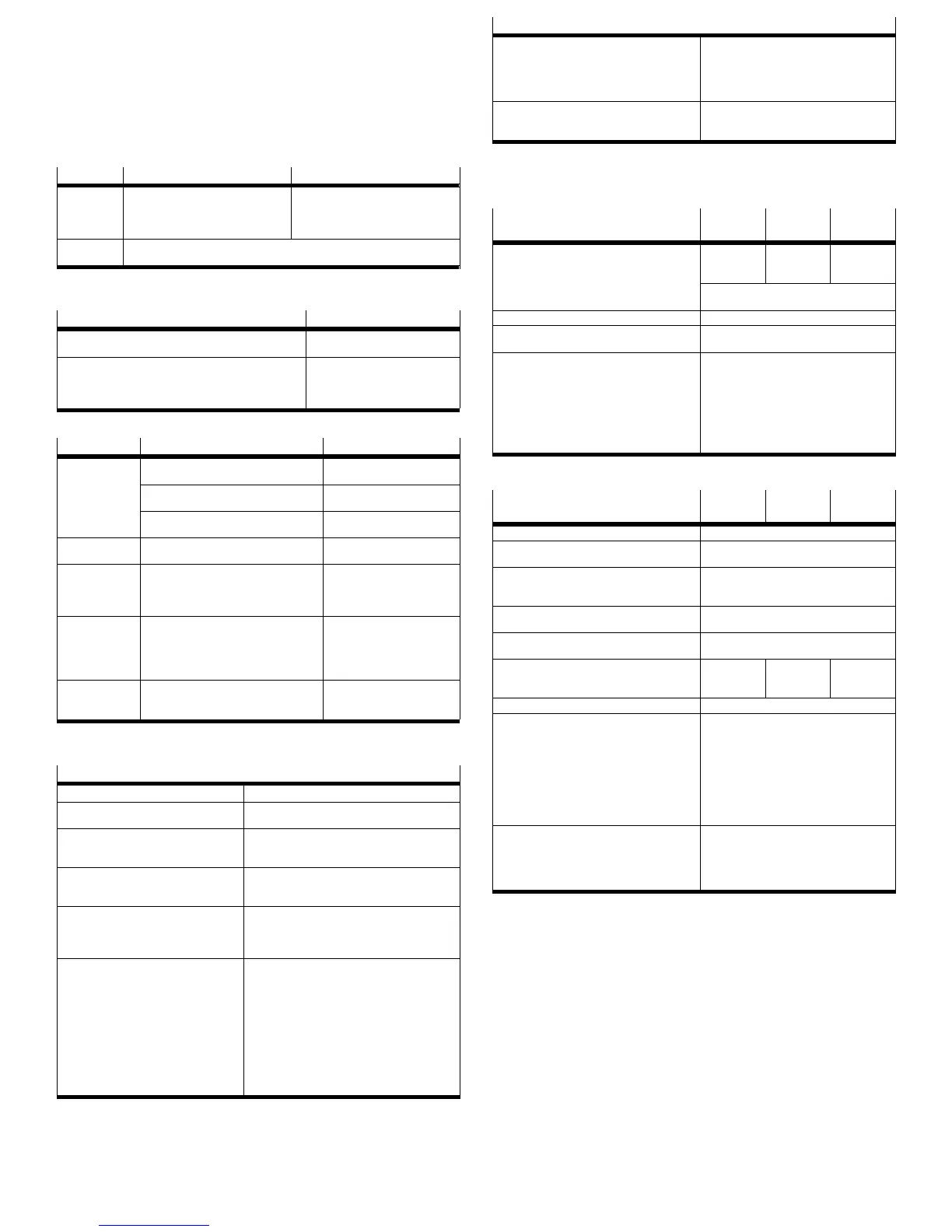
11 Safety setting
Wire break Voltage type Current type
Setpoint
value
Outlet pressure drops to 0 bar The last value is saved. The outlet
pressure is maintained unregulated. In
the medium term, the pressure at the
output can increase or diminish.
Supply
voltage
The last value is saved. The outlet pressure is maintained unregulated. In the
medium term, the pressure at the output can increase or diminish.
Fig. 34
12 Fault clearance
Cause Error display
– Value below limit value (setpoint value)
– Value exceeds limit value (setpoint value)
ER.09
ER.10
– Undervoltage in the 24 V operating voltage
– Overvoltage in the 24 V operating voltage
– Hardware error
– Temperature range exceeded in the VPPM-...C1
ER.05
ER.26
ER.01
ER.28
Fig. 35
Malfunction Possible cause Remedy
VPPM-...C1 does
not react
Supply voltage not applied; POWER LED
does not light up
Check connection of the 24 V
DC supply voltage
Setpoint voltage or setpoint current not
applied
Check controller
Check connection
VPPM-... C1 defective Send the device to the Festo
repair service
Flow rate too low Restriction of the flow cross section due to
connection technology (swivel fittings)
Use an alternative connec
tion
Pressure rise too
slow
Large cylinder volume and long tube
length
Select different parameter
record
Use VPPM-...C1 with larger
nominal width
Pressure constant
despite modified
setpoint specific
ation
– Supply cable breakage (the last set out
let pressure is maintained but not regu
lated. In the medium term the pressure
at the output can increase or diminish).
– Too little supply pressure P1
Replace supply cable
Increase supply pressure
UP/DOWN keys
on the VPPM-...C1
do not react.
Voltage is present at digital inputs D1
and D2
Apply 0 V DC to digital inputs
D1 and D2
Fig. 36
13 Technical data
General data
Design
Proportional pressure regulator valve
Mounting position Any, preferably horizontal
(display elements facing upwards)
Medium Compressed air in accordance with
ISO 8573-1:2010 [7:4:4]; inert gases,
operation with lubricated medium not possible
Degree of protection IP 65 when mounted, with tightened mounting
screws, in combination with plug socket according
to accessories.
Permissible temp. range
– Environment
–Medium
– Storage
[°C]
0 ... +50
+10 ... +50
–10 ... +70
Vibration and shock
– Vibration
– Shock
The following specifications do not apply to
mounting on the bracket VAME-P1-A.
Checked in accordance with DIN/IEC 68/
EN 60068 part 2-6;
for wall mounting:
0.35 mm path with 10 … 60 Hz
5 g acceleration with 60 … 150 Hz
Tested in accordance with DIN/IEC 68/
EN 60068 part 2-27
for wall mounting:
±30 g at 11 ms duration; 5 shocks per direction
General data
Materials
Housing
Cover
Seals
Lubrication
Wrought aluminium alloy
PAXMD6-GF50/gr-P, PA6-GB20,GF10/gr-P
Nitrile rubber
Silicone-free
Weight [g] 1/8”: 400
1/4”: 560
1/2”: 2050
Fig. 37
Pneumatics data 2 bar type
30 psi
6 bar type
90 psi
10 bar type
150 psi
Pressure ranges
– Permissible inlet pressure
– Control range
[bar]
0 ... 4
0.02 … 2
0 ... 8
0.06 ... 6
0 ... 11
0.1 ... 10
Inlet pressure p1 at least 1 bar above outlet
pressure p2
Total leakage when new [l/h] < 5
Ports G1/8” (1/8 NPT), G1/4” (1/4 NPT),
G1/2” (1/2” NPT)
Nominal width
– Pressurisation
– Exhaust
[mm]
With 1/8”: 6
With 1/4”: 8
With 1/2”: 12
With 1/8”: 4.5
With 1/4”: 7
With 1/2”: 12
Fig. 38
Data for the electrical components 2 bar type
30 psi
6 bar type
90 psi
10 bar type
150 psi
Electrical connection Pin contact M12x1, 8-pin
Permissible operating voltage [V DC] 21.6 ... 26.4 (permissible residual ripple
max. 10 %)
Max. electrical power consumption
– Nominal size 1/8” and 1/4”
– Nominal size 1/2”
[W]
7
12
Power rating of digital switching
output D3 (PIN 8 in el. connection)
[mA]
Max. 60
Max. permitted supply and signal line
length
[m]
10
Overall accuracy
– Standard (2 %) +0.5 x hysteresis
– Class S1 (1 %) +0.5 x hysteresis
[bar]
0.045
0.025
0.135
0.075
0.225
0.125
Hysteresis 0.5 % full scale
Voltage type VPPM-...-V1.-...C1
– Setpoint variable
– Input resistance (setpoint value)
– Load of actual value output
Current type VPPM-...-A4.-...C1
– Setpoint variable [mA]
– Input resistance (setpoint value)
– Load of actual value output
[V DC]
[kΩ]
[kΩ]
[m A]
[Ω]
[Ω]
0 ... +10
10
Min. 2
4 ... 20
250
Max. 500
Electromagnetic compatibility EMC
*)
– Interference emission and interfer
ence immunity
See declaration of conformity
è www.festo.com
CE conformity for industry environments
fulfilled
1) The valve is intended for use in an industrial environment. Outside of industrial environments, e.g. in
commercial and mixed-residential areas, actions to suppress interference may have to be taken.
Fig. 39
 Loading...