8
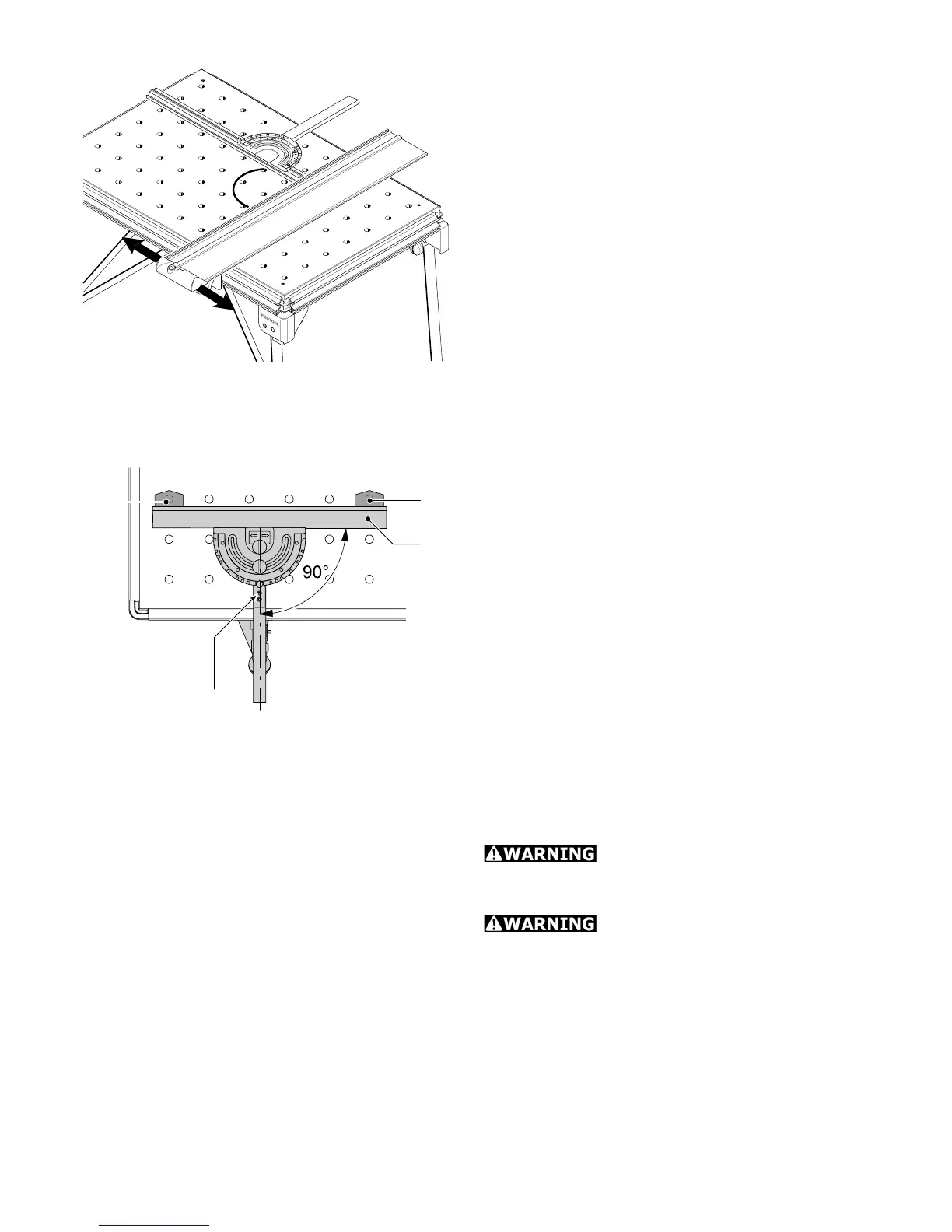
Step 6: Calibrating angle
Check the angle setting of the pre-set pro-
fi le setting rail before starting work. Align
the guide rail fi rst of all [Fig. 8].
Align the guide rail at right angles to the
pre-set profi le setting rail. If an angle of
90° is not possible, slide a support unit on
the guide rail until the angle is correct. Se-
cure the guide rail.
NOTE: Slide the relevant stop [4-3] along
the table profi le to retain the setting per-
manently.
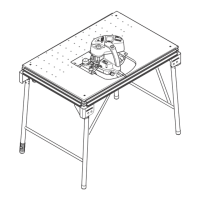
If required, the pre-set profi le setting rail
can also be aligned in relation to the per-
forated top provided the necessary clamps
(accessories) are available.
Insert the clamps [9-1] and [9-2] as shown
in Fig. [9] and move the stop ruler [9-3] to
a 90° position.
If the stop ruler does not rest evenly
against the clamps:
Loosen the screws [9-4] and the rotary
knob [7-2]. The retaining pin must be en-
gaged in the 90° notch.
Set the angle at 90° in relation to the
clamps and tighten the screws.
Step 7: Adjusting the pre-set
profi le setting rail
Risk of injury! Always use
the fence in a fi xed position and do not use
to slide the workpiece along!
Risk of injury! Make sure
that all rotary knobs on the fence are tight-
ened before starting work.
The fence can be adjusted in the following
ways:
9-2
9-1
9-3
9-4
9
8
90°