12.2
Connecting the DC Power Cable for th
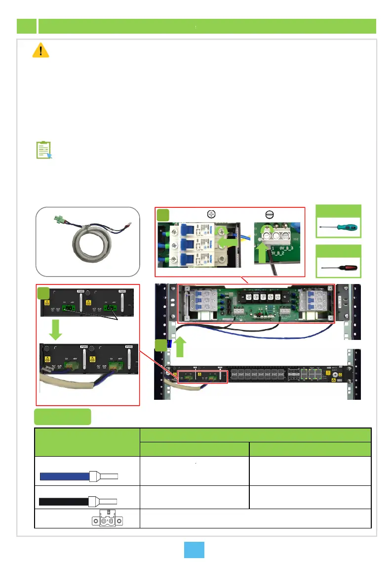
Caution
Before connecting the DC power cable for the equi
equipment on the PDP is placed in the OFF positi
Completely insert the cord end terminals into the t
metal part exposed should not exceed one sixth of
covering or metal part of the terminals in the same
Do not press the insulation covering of the cord en
Make sure the side with a larger area of the cord e
After you have completed connection of the power
ends of each cable, 1 cm to 2 cm away from the c
Equipment DC power cable
Connection of the DC power cables for the AN6001-
refer to the table below for details. The following intro
equipment when the PDP296B (3000068) is used.
Instruction
Cord end term
3
Connection
Two-conductor power plug
Power input interfaces
1
2
1
Cable Connector
Connected to
PDP260B (300006
Cord end terminal (-48 V, blue)
-48 V branch powe
terminal (P1 is the
the standby one)
Cord end terminal (0 V, black)
0 V branch power r
Two-conductor
power plug
Connected to the p
AN6001-G16.
Equipment
pment, make sure that the power control switch for the
n.
rminal blocks on the PDP. To ensure good connection, the
the overall metal length. The length of exposed insulation
row or batch should be equal whenever possible.
terminals, which may result in poor electrical connection.
d terminal contacts with the terminal block.
cable, attach a label indicating the cable information to both
nnector on each end.
Cross
screwdriver
Flat
screwdriver
16 on the PDP side may vary with the PDP used. Please
uces how to connect the DC power cable for the
M5
nal (-48 V, blue)
Cord end terminal
(0 V, black)
M4
) PDP296B (3000068)
rail output
ctive one and P2
-48V_A_1 to -48V_A_3 terminals (active)
-48V_B_1 to -48V_B_3 terminals (standby)
il output terminal
0V_A_1 to 0V_A_3 terminals (active)
0V_B_1 to 0V_B_3 terminals (standby)
wer input interface on the DC power module (PWRD) of the
 Loading...