Instruction
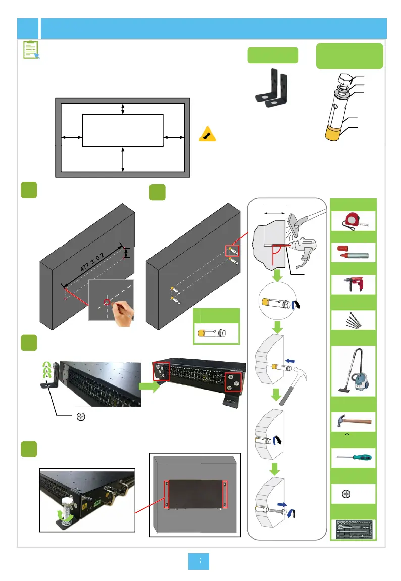
To facilitate air cooling of the equipment and us
operation on it, provide the required installation
as indicated in the figure below (in this example
front side of the equipment faces downward) w
mounting the equipment on the wall.
AN6001-G16
≥30
≥80≥80
Rear side of
the equipment
6
Mounting the Equipment on the
Determine the position and
direction of the equipment
on the wall, and mark the
mounting holes with a
marker pen.
Install the
bolt.
≥60
≥300
Front side of
the equipment
1
2
174.5 ±0.2
s
cl
v
Install the wall mounting
ears.
Unit: mm
3
screwM4
Tighten the bolts with a socket wrench.
4
rs’
paces
the
en
Component
Wall mounting ears
Assembly of the
Expansion Bolt
nit: mm
(1)
(3)
(2)
(4)
(5)
all
Note
Ф14.5
expansion
Electric drill
Marker pen
Long tape
(1) Hex machine screw M8 x 60
(2) Spring washer
(3) Flat washer
(4) Expansion sleeve
(5) Expansion nut
Unit: mm
≥60
90°
e equ
pmen
room
ould be dry and
ean with good
ntilation as required.
Drilling bit
Vacuum
cleaner
Claw
hammer
M8
Expansion
bolt
Socket
wrench
M4
Screw
ross
screwdriver
 Loading...