WARNING
• TURN OFF INCOMING POWER BEFORE SERVICING EQUIPMENT.
• ALL INSTALLATION AND MAINTENANCE WORK MUST BE PERFORMED BY
QUALIFIED ELECTRICAL PERSONELL ONLY.
• VERIFY ALL ELECTRICAL RATINGS BEFORE INSTALLATION IS COMPLETE.
LOCATION
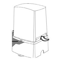
Install the WPC-2 enclosure using the mounting plates included with each enclosure. The
WPC-2 is housed in a Type 3R rainproof enclosure and can be mounted anywhere between the
ool e
ui
ment and the breaker
anel.
WIRING INSTRUCTIONS
FOLLOW PROPER WIRING PRACTICES IN ACCORDANCE WITH ALL LOCAL
REGULATORY REQUIREMENTS.
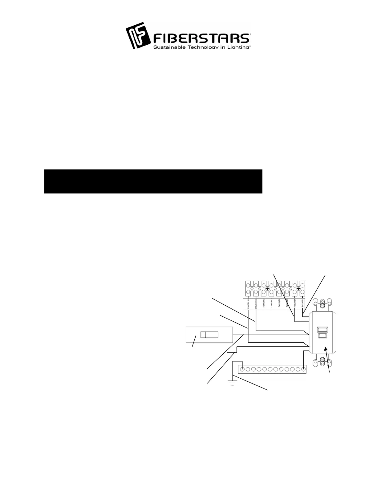
Power Connections:
To wire the WPC-2 use insulated
COPPER wire only, 12 gauge m
Run a ½” to ¾” conduit from the ma
breaker panel to the WPC-2. Pull
appropriate wires from the main breaker
panel to the WPC-2 unit. To make
power connections remove 3/8 inches of
insulation from wire ends. Connect b
wires to the Load Center as illustrated.
Tighten terminal screws firmly (20 lb-in
minimum). Connect the common to the
Neutral bar (tighten to 20 lb-in
minimum). Install a 20 Amp circuit
breaker and wire to the 120V LINE a
the T/C POWER of the terminal blo
Wire the Neutral and T/C NEUTRAL
terminals to the Neutral bar on the Load
Center. For use with an internal GFCI,
punch out the GFCI knockout on the
Load Center Cover Plate of the WPC
Install a GFCI with appropriate
hardware (sold separately from
Fiberstars, part number WPC-2/3 ST).
in
are
nd
ck.
.
TO
EUTRAL BAR
DE
GROUND
HOT
LINE SI
T/C
EUTRAL
T/C POWER
HOT
LOAD SIDE
EUTRAL
LOAD SIDE
GFCI
120VAC 20AMP
ERCIRCUIT BREAK
inimum.
79-15054-00 Rev. C http://www.fiberstars.com Page 6 of 18
 Loading...