Technical Service: 800.742.8368 • fieldcontrols.com 33
SPECIFICATIONS
MODEL
CONTROL
SIZE
NOMINAL
CAPACITY
(SQ. IN.)
RECOMMENDED PIPE SIZES (IN.) DIMENSIONS (INCHES)
Dia. Circum. A B C D E F G H J K L M
10" M+MG2*
10 78.5 9 - 10 28
1
⁄4 to 31
1
⁄2 10 4
3
⁄8 5 4
1
⁄4 11 3
3
⁄8 1
1
⁄8 4
3
⁄4 1 3
1
⁄2 1 14
1
⁄8
12" M+MG2*
12 113 11 - 12 34
1
⁄2 to 37
3
⁄4 12 5
3
⁄4 6 5 13
1
⁄4 4
5
⁄8 1
3
⁄4 4
3
⁄4 1 3
1
⁄2
7
⁄8 16
1
⁄2
14" M+MG2*
14 154 13 - 14 40
3
⁄4 to 44 14 7
1
⁄8 7 5
3
⁄4 15
1
⁄2 5
3
⁄8 2
1
⁄8 5
1
⁄8 1 3
1
⁄2
5
⁄8 19
1
⁄4
16" M+MG2
16 201 15 - 16 47 to 50
1
⁄4 16 8
3
⁄8 8 6
1
⁄2 17
1
⁄2 6
1
⁄8 2
3
⁄8 5
5
⁄8 1
1
⁄2 4
5
⁄8 22
18" M+MG2
18 255 17 - 18 53
1
⁄2 to 56
1
⁄2 18 8
1
⁄4 9 7
1
⁄2 19
1
⁄2 6
7
⁄8 2
3
⁄4 7
3
⁄8 1
1
⁄2 5
1
⁄4 1
5
⁄8 24
5
⁄8
20" M+MG2**
20 314 19 - 21 59
3
⁄4 to 66 20 9
5
⁄8 10 8
1
⁄8 22 7
5
⁄8 3 7
3
⁄4 1
1
⁄2 6
1
⁄4 1
1
⁄4 27
3
⁄8
24" M+MG2**
24 452 22 - 25 69 to 78
1
⁄2 24 12
3
⁄8 12 10
1
⁄2 26 9
1
⁄4 3
5
⁄8 8
5
⁄8 2 6
1
⁄4 1
1
⁄4 33
28" M+MG2**
28 616 26 - 30 81
3
⁄4 to 94
1
⁄4 28 13
1
⁄8 14 - 30
1
⁄2 10
3
⁄4 4
1
⁄8 11
3
⁄8 2 6
1
⁄4
7
⁄8 38
1
⁄2
32" M+MG2**
32 804 31 - 34 97
1
⁄2 to 107 32 15
3
⁄8 16 - 35 12
1
⁄4 4
3
⁄4 12
1
⁄8 2 6
1
⁄4
5
⁄8 43
1
⁄2
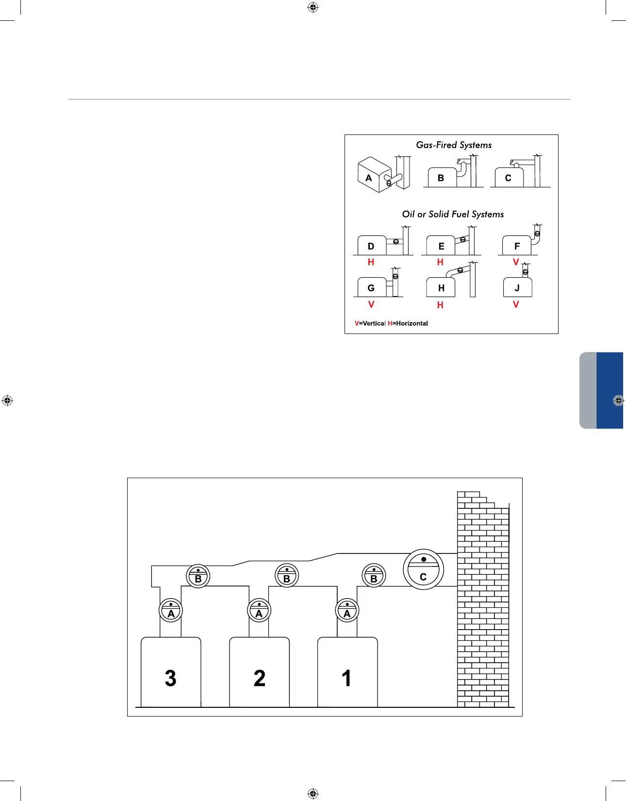
For gas-fired equipment, the preferred location of the control is
on the bull head tee. This location provides maximum relief of
downdrafts with minimum positive pressure.
(See Figure 1, Diagram A-C)
With oil or solid fuels, the bull head tee is not recommended,
so locate the control as shown. (See Figure 1, Diagram D-J)
These locations are acceptable for gas units as well. Except on
forced draft systems, locate the control as close as possible to the
furnace or boiler, at least 12" beyond a stack switch on oil-fired
units, and at least 18" from a combustible ceiling or wall.
Commercial and industrial furnaces and boilers are frequently installed in multiples. (See Figure 2) Use a draft control for each
boiler located on the uptake between the smoke outlet and the breach (location A). When this uptake is too short to permit the
installation of a control, locate a separate control for each boiler on the main breach (location B). If neither of these locations
is possible, use a single large control in the breaching between the chimney and the nearest boiler (location C). Where several
units are vented into a common breaching, the most draft-critical should vent highest in, or be placed closest to the chimney.
Incinerators should generally be placed farthest from, or vented lowest in the chimney.
MULTIPLE APPLIANCE LOCATION RECOMMENDATIONS
FIGURE 1
Figure 2
RECOMMENDED LOCATIONS FOR FIELD DRAFT CONTROLS
INSTALLATION OPTIONS
DRAFT CONTROL


 To Next Page