Mounting
adjustment of the AKAS® at the first installation
fine adjustment
5
5.7
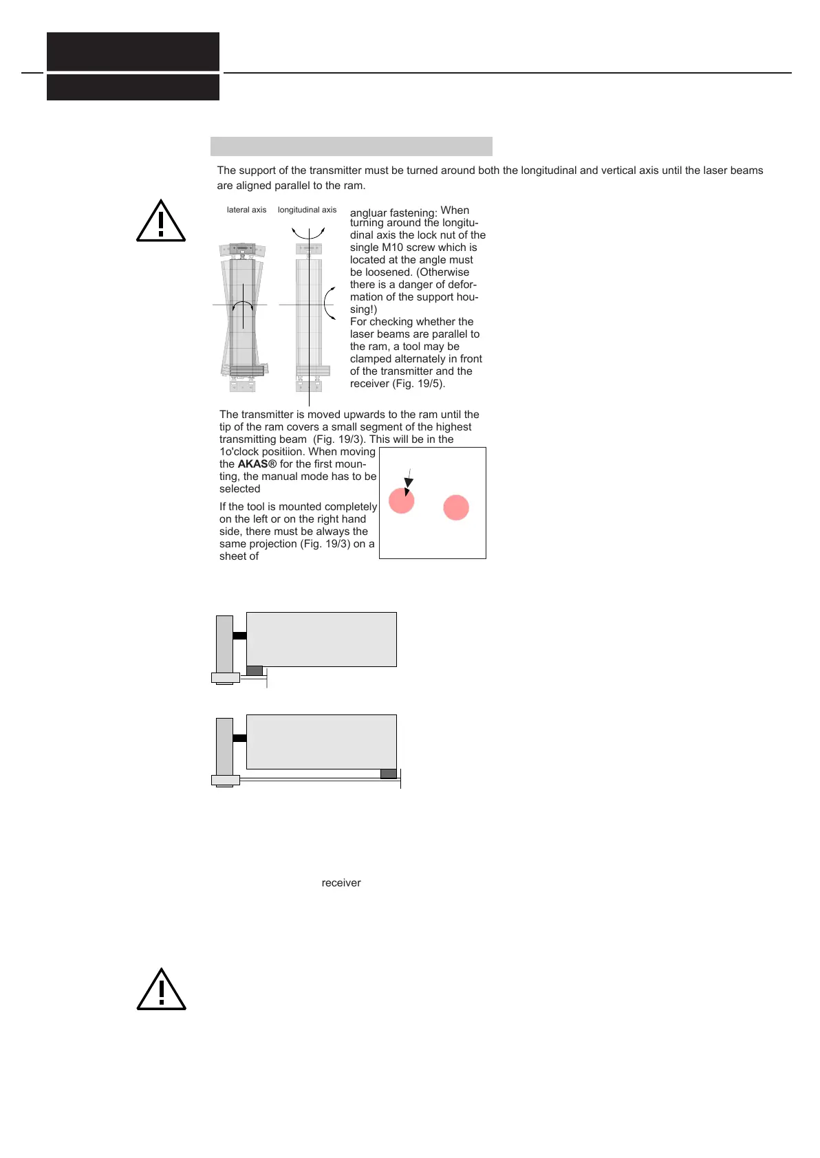
lateral axis longitudinal axis
angluar fastening:
When
turning around the longitu-
dinal axis the lock nut of the
single M10 screw which is
located at the angle must
be loosened. (Otherwise
there is a danger of defor-
mation of the support hou-
sing!)
For checking whether the
laser beams are parallel to
the ram, a tool may be
clamped alternately in front
of the transmitter and the
receiver (Fig. 19/5).
The support of the transmitter must be turned around both the longitudinal and vertical axis until the laser beams
are aligned parallel to the ram.
The transmitter is moved upwards to the ram until the
tip of the ram covers a small segment of the highest
transmitting beam (Fig. 19/3). This will be in the
1o'clock positiion. When moving
the AKAS® for the first moun-
ting, the manual mode has to be
selected
If the tool is mounted completely
on the left or on the right hand
side, there must be always the
same projection (Fig. 19/3) on a
sheet of paper held behind the
tool (Fig. 19/5).
This check must be done with the highest (biggest)
and lowest (smallest) tool.
Fade-out
Ram
Ram
tool pos.1
tool pos. 2
transmitter
paper
tool
tool
Fig. 19/5
paper
Then, the transmitter is carried upwards by pressing
the button "transmitter up/down". This action makes
the receiver follow.
When the highest highest position is reached, plea-
se check whether the receiver is also free and whet-
her the transmitting beams meet the receiver as
shown in Fig. 19/3. By this it is guaranteed that both
transmitter and receiver move parallel to each other
and to the bending line.
Doku Nr. 1379 Stand 27.1.2017 /Aui
Sending rays image on
white paper
-AKAS®-3...
FIESSLER
E L E K T R O N I K
It is important to note that the marker line is only a rough guide. After the coarse adjustment is finished please
activate the box bending mode and do the following tests:
a) an object which protrudes 3mm beyond the bending line into the machine must be detected
b) an object which protrudes 2mm beyond the bending line into the machine must not be detected
If a) is not met, the transmitter and receiver must be adjusted further forward towards the operator.
If b) is not met, the transmitter and receiver must be adjusted further backward, away from the operator.