Mounting
Adjustment of the AKAS® at the first installation
6. Adjustment of the
AKAS®
at the first installation
adjustment of the receiver
adjustment of the transmitter
5
5.7
both supports must be mounted in a way that:
1. the highest (biggest) bending punch and the smallest
bending puch is within the range of the supports.
2. using the smallest bending punch, the receiver
element E1+Z (AKAS®-3 see fig. 18/1) are covered by
the punch at the highest range position of the support.
3. using the highest bending punch, the receiver element
E1+Z (AKAS®-3 see fig. 18/1) can still be positioned
correctly at the lowest position.
Adjust the support with the help of a spirit level vertically,
i.e. parallel to the guiding rails of the ram.
Set up the receiver with the M6 adjustment screws until
the white line on the receiver cover is in line with the
bending line of the machine.
Verify that the white line on the receiver is in line with
the bending line all over the entire movement range of
the receiver support.
Check this over during the whole travel of the support of
the receiver by turning the key-operated switch to "ON"
and carrying the receiver upwards with pressing the but-
ton "RECEIVER UP". For doing this, the adjustment mo-
de must be in manual mode s. chap. 5.8.). During the up-
ward movement of the receiver, repeatedly turn the key-
operated switch to "OUT" and check the distance bet-
ween the mark and the perpendicular (bending line) to
make sure that the receiver is carried up parallelly to the
bending line. The displacement by the motor is not inten-
ded for nonstop carrying up and down. In this case the
thermal protection switches off the motors. After letting go
the button and a short brake you may continue the carry-
ing procedure.
Set up the transmitter with the M6 adjustment screws
until the white line on the transmitter cover is in line
with the bending line of the machine.
Verify that the white line on the
transmitter is in line with the bending
line all over the entire movement
range of the transmitter support.
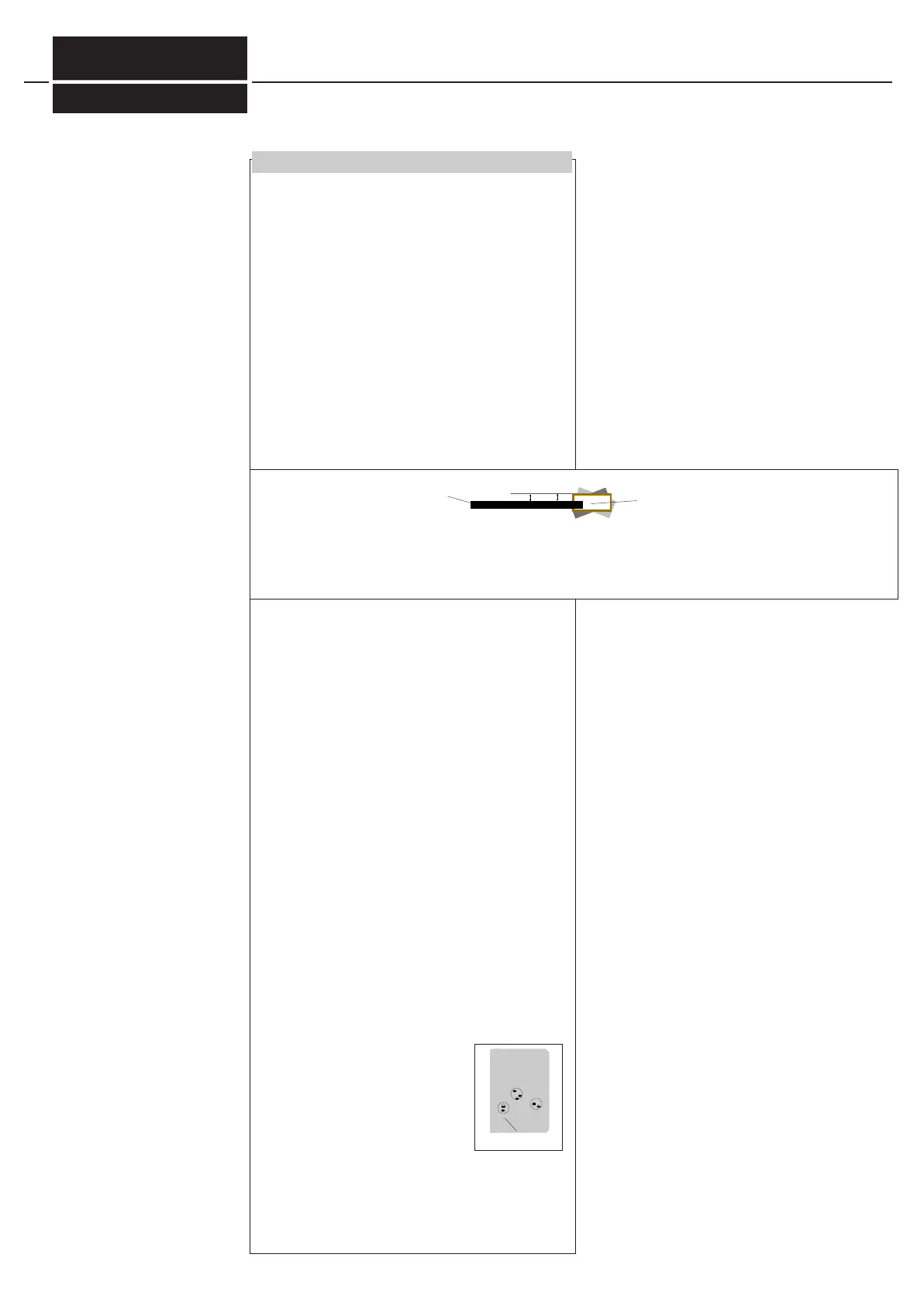
The red transmitting beams should
meet the receiver like it is shown in the
opposite illustration. When doing so,
please observe that the receiver stays
in the lower stop of the support. To check this, cover the
transmitter entirely. Then the receiver should not move
further downwards. The adjustment mode must be in ma-
nual mode (s. chap.5.8.)
Transmitter and receiver must be mounted at the same
height if both are installed in the lowest position of the
supports.
The receiver and the transmitter must be swiveled around the longitudinal axis in a way that their housings are pla-
ne parallel to the ram. With pivoting around the longitudinal axis, the adjustment screw or the locknut that counte-
racts the screwing movements, must be loosened.
Ram
receiverhousing
Fig.18/1
transmitter beams
AKAS®-3 Fig.18/3
-AKAS®-3...
FIESSLER
E L E K T R O N I K
Doku Nr. 1379 Stand 27.1.2017 /Aui