Instead of using a rear protective metal grid, a safety light grid with equivalent switching outputs, e.g.
type Fiessler ULVT / TLVT or ULCT / TLCT as shown in wiring diagram 6/p.33 is possible.
As alternative, the connection of a light grid with antivalent switching outputs is also possible, like p.e. the
Fiessler light grid EU2K 500/2. Wiring Diagram 7/p.33 shows the connection of the Fiessler light grid
EU2K 500/2 as a rear safeguard. In this case, the switches of the lateral protective grids must have anti-
valent switching contacts (1 normally closed and 1 normally open contact each) and the operating mode
with antivalent switching protective door circuits must be selected. In this case, the connector 1 at the
transmitter of the EU2K 500/2 must be wired to the output S_EU2K of the AKAS®.
The lateral protective grids are not monitored. Every switching-over of the selector, the reset buttomn
must be activated for the Emergency-OFF circuits and the circuits of the lateralprotective doors.
6a. Rear safeguarding
with lightgrid
with equivalent switching outputs
6b. Rear safeguarding
with lightgrid
with antivalent switching outputs
Electrical connections - Description / Wiring diagrams
6
-with integrated safety functions
6.4.1
NA1 NA3NA2 EDMO
.
.
.
FUO
.
.
.
wiring diagram 6/p.33
NA1 NA3NA2 EDMO
.
.
.
FUO
.
.
.
1
62 5
EU2K 500/2-R
1
5
EU2K 500/2-R
S_EU2K
wiring diagram 7/p.33
right lateral protec-
tive grid (open)
left lateral protective
grid (open)
Emergency OFF 1
Emergency OFF 2
Reset button
for light grids
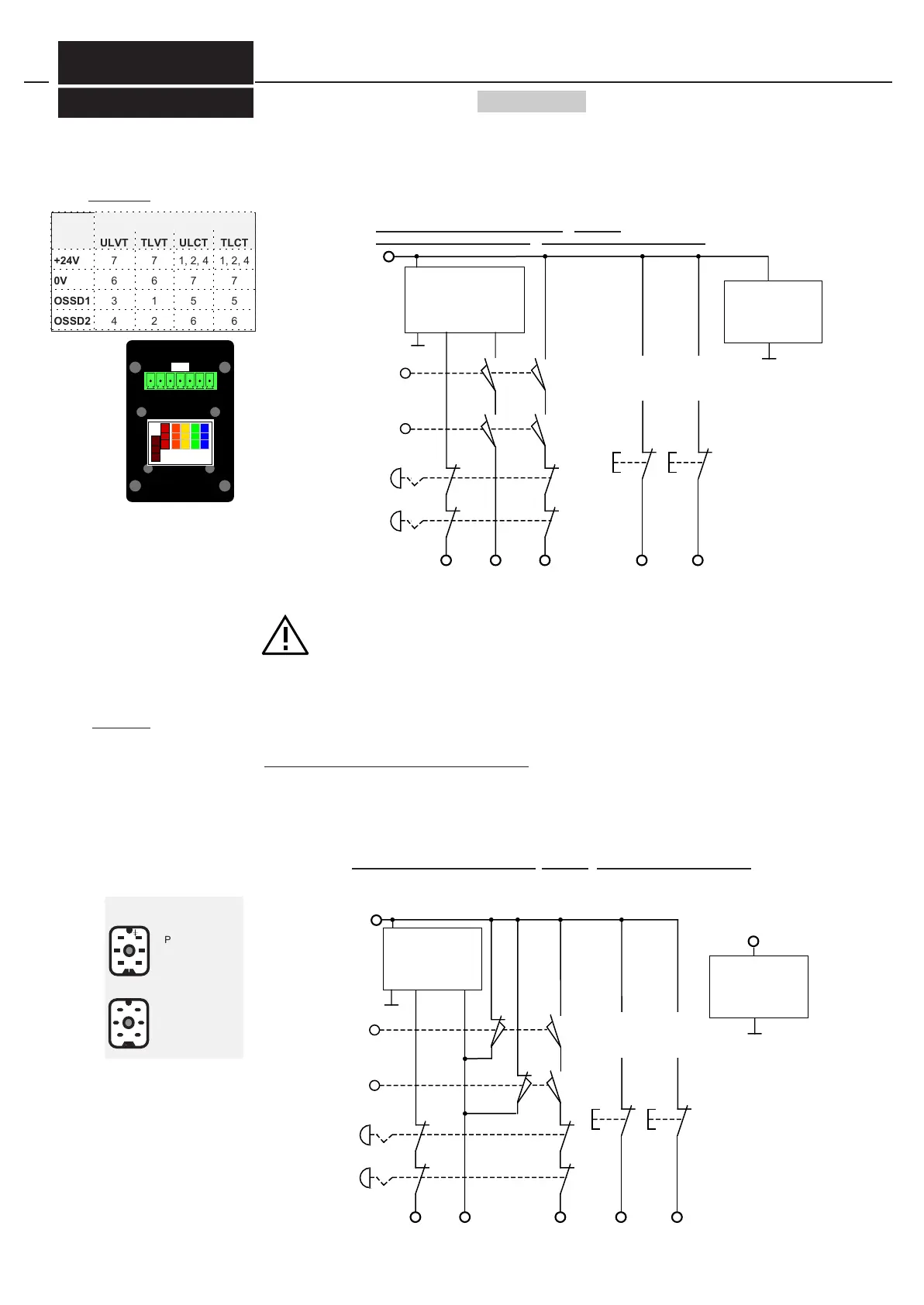
Protective doors and emergency OFFs and light grid EU2K 500/2 for rear safeguarding
at operating mode antivalent protective door control pairs
with EDM / with monitoring of the foot pedal
+24V
receiver
Reset button
for Emergency
OFF, lateral
protective grids
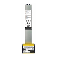
Protective doors and emergency OFFs and light grid ULVT / TLVT or ULCT / TLCT for rear safeguarding
at operating mode equivalent protective door control pairs
/ with EDM /
with monitoring of the foot pedal
/ with Start interlock for the lightgrid
emergency OFF 1
emergency OFF 2
Reset button for
Emergency OFF,
lateral protective
grids
right lateral protec-
tive grid (open)
left lateral protec-
tive grid (open)
Reset button
for light grid
depending on
operation mode
further contacts
transmitter
ULVT / TLVT:
Dip-switches (see picture)
-without restart interlock
-without EDM
-OSSD equivalent
ULCT / TLCT:
programming the operation mode
of the lightgrid:
-without restart interlock
-without EDM
+24V
0V
7
6
7
6
1, 2, 4
7
1, 2, 4
7
Pin 1 : + 24 V DC
Pin 5 : - Ub
Pin 1 : + 24 V DC
Pin 2 : A1
Pin 5 : A2
Pin 6 : - Ub
plug EU2K emitter 24 V
plug EU2K receiver
+UB
ULVT / TLVT
ULCT / TLCT
emitter
0V
+UB ULVT / TLVT
ULCT / TLCT
receiver
0V OSSD1 OSSD2
+24V
FIESSLER
E L E K T R O N I K
Receiver
Doku Nr. 1379 Stand 27.1.2017 /Aui
Only to use the operation modes D...D... or F...F...!
These modes activates Start interlock for the rear safety lightgrid! (see chapter 6.5.2)
If the connected lightguard does not detect all possible cross circuit and short circuit on the out-
puts OSSD 1 and OSSD2 you have to wire them in a way that no cross and short circuit is possible.