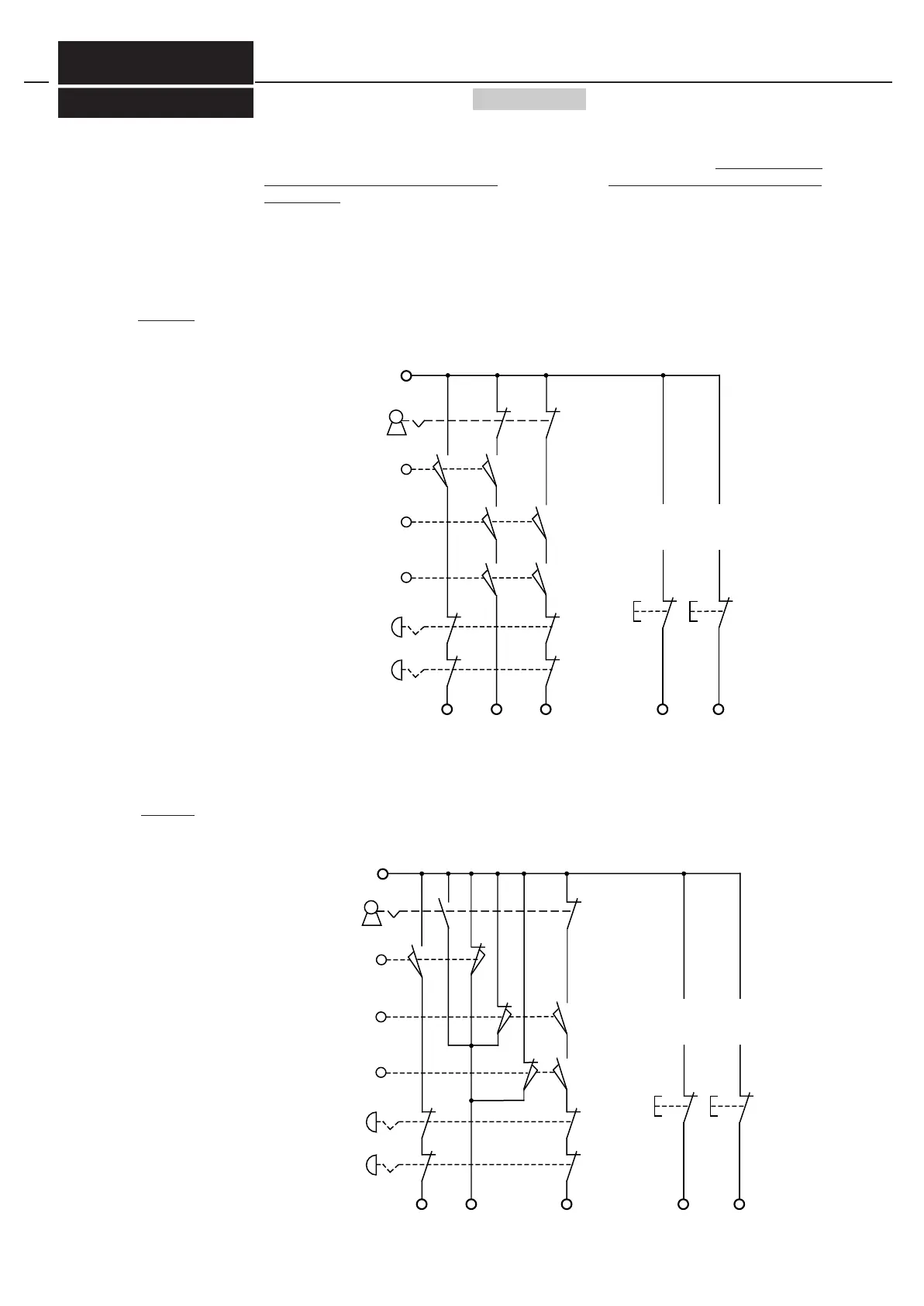
A selector switch provides the possibility to choose between operating mode with activated protective
field of the AKAS® and fast closing speed or operating mode with protection only by monitored slow
speed closing, see Wiring diagrams 8/p.34 und 9/p.34. If the selector switch is activated, the protective
field of the AKAS® is muted (bridged). This state is displayed by the shining muting lamp. By disabling
of its output SGA , AKAS® requires the NC to carry out only cycles in slow speed, which is monitored
by the AKAS®. Given the fact that in this operating mode, only cycles in slow speed are possible, the la-
teral protective grids are not monitored. Every switching-over of the selector, the reset buttomn must be
activated for the Emergency-OFF circuits and the circuits of the lateralprotective doors.
7. Installation operating mo-
de, i.e. protection by monito-
res slow speed without acti-
vated protective field
during operation with door
monitoring
operation with equivalent switching
protective door contacts
operation with antivalent
switching
protective door contacts
Electrical connections - Description / Wiring diagrams
6
-with integrated safety functions
6.4.1
Doku Nr. 1379 Stand 27.1.2017 /Aui
NA1 NA3NA2 EDMO
.
.
.
FUO
.
.
.
+ 24V
Wiring diagram 8/p.34
Emergency OFF 1
Emergency OFF 2
Reset button for
Emergency OFF,
lateral protective
grids and selector
switch
operation with activated protective field of the AKAS® and slow speed closing movement (selector not activated)
operation with only protection by monitored slow speed closing movement (selector switch activated)
selector switch
not activated
right lateral protec-
tive grid (open)
left lateral protecti-
ve grid (open)
rear protective
grids (open)
depending on
operation mode
further contacts
Reset button for
rear protective
grids
NA1 NA3NA2 EDMO
.
.
.
FUO
.
.
.
+24 V
Wiring diagram 9/p.34
Reset button for
Emergency OFF,
lateral protective
grids and selector
switch
Reset button for
rear protective
grids
depending on
operation mode
further contacts
Emergency OFF 1
Emergency OFF 2
selector switch
not activated
right lateral protec-
tive grid (open)
left lateral protecti-
ve grid (open)
rear protective
grids (open)
operation with activated protective field of the AKAS® and slow speed closing movement (selector not activated)
operation with only protection by monitored slow speed closing movement (selector switch activated)
AKAS®-3PF
FIESSLER
E L E K T R O N I K


 To Next Page