D500-74-00 2 I56-2463-008
TESTING
The following resistance values can be used to test the module after installation:
Short Circuit: <50Ω
Open Circuit: >1MΩ
Ground Fault: <50Ω
All relay switch contacts are shipped in the standby state (open) state, but may
have transferred to the activated (closed) state during shipping. To ensure that
the switch contacts are in their correct state, modules must be made to com-
municate with the panel before connecting circuits controlled by the module.
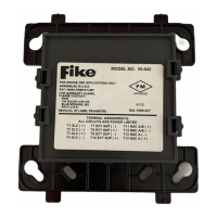
TERMINAL DEFINITIONS
T1 (+) SLC in/out T9 (–) External Power Line in/out
T2 (–) SLC in/out T10 (+) External Power Line in/out
T3 (+) SLC in/out T11 (+) NAC A/B
T4 (–) SLC in/out T12 (–) NAC A/B
T7 (–) External Power Line in/out T13 (–) Class A
T8 (+) External Power Line in/out T14 (+) Class A
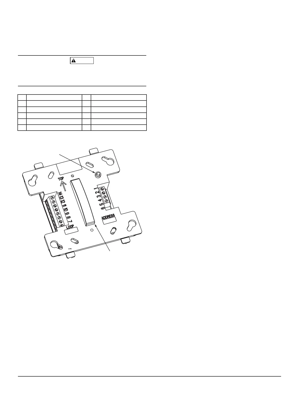
FIGURE 1. SUPERVISED CONTROL MODULE:
LED INDICATOR
IR RECEIVER
C0164-00