Do you have a question about the Fike Cheetah Xi 50 and is the answer not in the manual?
Highlights critical safety warnings and cautions to prevent hazards to personnel and equipment.
Details the system's general, power, and signaling line circuit features and functionalities.
Detailed description of the Cheetah Xi 50 controller board, its functions, and internal components.
Overview of intelligent detectors, their communication, and addressable features.
Details the photoelectric smoke detector's operation, features, and configurable modes.
Details the ionization smoke detector's operation, features, and configurable modes.
Describes the combined photo/heat detector, its features, and operational modes.
Details the heat detector's operation, set-point ranges, and configurable modes.
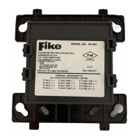
Overview of addressable modules for interfacing devices with the control panel.
Describes the addressable manual pull station for initiating alarm inputs.
Details the SCM for switching notification appliances and monitoring power status.
Describes the RCM for interfacing solenoids and agent release modules.
Lists equipment and software used for system configuration, programming, and testing.
Information on backup batteries and enclosures required for system power.
Presents a checklist of general steps for installing the Cheetah Xi 50 system.
Guidance on selecting appropriate wire types and sizes based on electrical codes and standards.
Explanation of Class B, Class A, and Class X wiring configurations for system circuits.
Procedures for testing field wiring integrity prior to connecting system devices.
Steps for installing internal components such as the transformer and controller.
Instructions for mounting the AC power transformer within the enclosure back-box.
Steps for safely connecting AC power to the system's main transformer.
Steps for mounting the Cheetah Xi 50 controller board onto the enclosure stand-offs.
Procedure for connecting the transformer's secondary output to the controller's AC input terminals.
Instructions for installing the system's backup batteries and connecting them.
Procedure for applying power to the controller and performing initial operational checks.
General guidance for connecting various field wiring to the controller's terminal blocks.
Instructions for wiring peripheral devices to the panel's RS485 peripheral bus.
Instructions for wiring the Signaling Line Circuit (SLC) to addressable devices.
Typical Class B wiring for the SLC loop, illustrating a non-redundant path.
Wiring details for Notification Appliance Circuits (NACs) to activate signaling devices.
Procedure for initial system power-up after all field wiring is connected and verified.
Describes methods for configuring the Cheetah Xi 50 system, including Auto Program.
Details the process for system testing and acceptance to verify compliance with standards.
Details the indicators and steps for responding to a system alarm condition.
Describes indicators and steps for handling trouble or supervisory conditions.
Resets the control panel to normal operation after conditions are cleared.
Emphasizes the importance of regular system inspection and testing per NFPA and local standards.
Provides Fike Corporation's Customer Service contact details for troubleshooting assistance.
| Brand | Fike |
|---|---|
| Model | Cheetah Xi 50 |
| Category | Control Systems |
| Language | English |