Do you have a question about the Fike 55-042 and is the answer not in the manual?
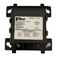
The Fike 55-042 Supervised Control Module is a versatile device designed to integrate and manage notification appliances within a fire alarm system. Its primary function is to switch an external power supply or audio amplifier to these appliances, enabling them to activate during an alarm event. Beyond simple switching, the module incorporates advanced monitoring capabilities to ensure the integrity and reliability of the connected circuits.
One of the key usage features of this control module is its ability to monitor the wiring to auxiliary devices for open and short circuits. This supervision is crucial for maintaining a robust fire alarm system, as it allows for early detection of wiring faults that could prevent notification appliances from activating when needed. This monitoring is achieved through the use of an end-of-line resistor, which helps the module detect changes in circuit resistance indicative of a fault. The module supports both Class A and Class B wiring operations, offering flexibility in system design and installation to meet various code requirements and building layouts.
The 55-042 module also includes a capability to monitor the external power input for loss of power, specifically for DC voltage supplies. This feature is vital for systems that rely on external power sources for their notification appliances, ensuring that any interruption to this power is detected and reported. This power loss monitoring can be enabled or disabled through device configuration programming, allowing installers to tailor the module's behavior to specific system needs.
A sophisticated algorithm is integrated into the module to handle scenarios where external power is switched to auxiliary devices and a DC supply loss occurs. In such a situation, the control module can switch back to monitor mode to check the line for short circuits. If no short circuit is detected, the device will then reapply the external power. This intelligent recovery mechanism helps to restore system functionality automatically after a temporary power disruption, minimizing downtime and ensuring continuous protection. This algorithm can be activated when using a DC external supply that is guaranteed to maintain a voltage above 9 volts, ensuring reliable operation of this recovery feature.
For installation, the module is designed to mount directly into standard 4-inch square electrical boxes, requiring a minimum depth of 2 1/8 inches. Proper mounting is important, with the arrow on the module facing upward to ensure correct operation of the IR programming tool. Fike also offers surface-mounted electrical boxes (SMB500) as an accessory for installations where flush mounting is not feasible.
Wiring the 55-042 module requires adherence to applicable local codes, ordinances, and regulations. Installers must follow job drawings and appropriate wiring diagrams. For new installations, the module comes with a 39 kΩ end-of-line (EOL) resistor. However, for retrofit applications where an existing 47 kΩ EOL resistor is already in place and cannot be easily replaced, it can be left without compromising performance. This flexibility simplifies upgrades and maintenance in existing systems. An optional EA-CB barrier may be necessary to separate power-limited and non-power-limited wiring within the electrical box, ensuring compliance with safety standards.
Addressing the module is a straightforward process, performed using a handheld IR programmer according to the job drawings. Once addressed, the module is secured to the electrical box.
Maintenance features include testing procedures to verify the module's integrity after installation. Installers can check for short circuits, open circuits, and ground faults using specified resistance values. It's important to note that all relay switch contacts are shipped in a standby (open) state but may have transferred to an activated (closed) state during shipping. To ensure the correct state of the switch contacts, modules must be made to communicate with the control panel before connecting any circuits controlled by the module. This pre-connection communication ensures that the system starts with all components in their expected operational state, preventing potential issues during initial setup.
The module's compatibility requirements emphasize that it must be connected to a listed compatible control panel to ensure proper operation. This ensures seamless integration and reliable communication within the overall fire alarm system. The detailed terminal definitions provided in the manual guide installers in correctly connecting the SLC (Signal Line Circuit), external power lines, and NAC (Notification Appliance Circuit) wiring for both Class A and Class B configurations, as well as for audio amplifier applications. This comprehensive guidance facilitates accurate and compliant installation, which is critical for the long-term reliability and safety of the fire alarm system.
| Brand | Fike |
|---|---|
| Model | 55-042 |
| Category | Control Systems |
| Voltage Rating | 24 VDC |
| Material | Plastic |
| Certifications | UL |