Page 5
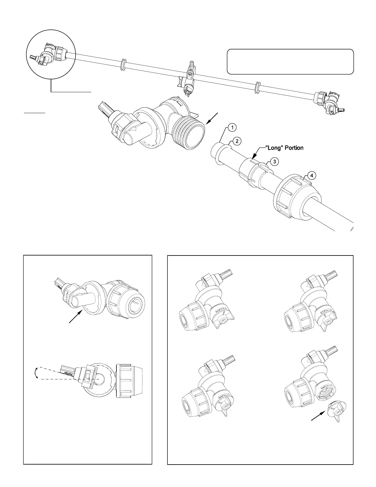
1. Start by sliding Items 4, 3, 2 onto the boom tube (Item 1)
as shown. First slide Item 4 on to the tube. Next slide Item 3
on to the tube, making sure the “Long” portion is facing the nozzle
end. Remove Item 2 from nozzle body and place on boom tube about
a 1/2” to 3/4” from the end of the tube.
2. Slide the (complete) end nozzle assembly onto the stainless steel boom tube,
with a somewhat “twisting” motion, so that the end face of the boom tube “butts”
up against the surface face inside the nozzle body.
3. Now push the “compression olive” (Item 3) against O-ring (Item 2) and slide
(both) into the nozzle body opening firmly.
4. Firmly tighten flynut (Item 4) onto threads of nozzle body.
Repeat for other side.
NOTE: If water is shooting back on the boom tube, item 2 is not in the correct placement.
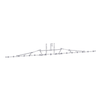
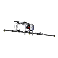
End Nozzle Assembly Procedure
For Boomless “Wet”Boom
Your boom will come with the (2) end nozzle assemblies
NOT affixed to your boom tube. Follow the instructions
below to attach these properly to the boom tube, as
shown.
Assembled
End Nozzle
15°
End Nozzle Informaon
(5275122)
This nozzle mounng stem
Has a ratcheng moon.
** Each “click” of the ratcheng moon is approx. 15° **
For proper/opmal spray coverage,
The nozzle must be at a 15° angle
The 15° angle shown will prevent the outer
Nozzles from overlapping with the center nozzle.
“On/O” Valve Posions
Valve “Open” Valve “Closed”
Service Posion On/O Valve Knob
Eliminate line pressure, then pull out
to check diaphragm condion.
Note: The check valve & diaphragm can fall out during transport, if the
knob is not turned to the “ON” or “OFF” posion.
Step 7
Item 2 is shipped inside of
the end nozzle assembly.
Remove & place on tube.