21
23
24
Fig.2A
28
27
29
26
TM 230 - TM 260
23
24
22
33, 34
25
21
F
ig.2A
28
27
29
26
TM 300- TM 350
Fig.2A
28
27
27
29
26
20
TM 320W
TM 360W - TM 420W
TM 500W - TM 650W
17. H²O out: Only to be used with the “liquid
cooling” option
18. H²O in: Only to be used with the “liquid cool-
ing” option
19. TORCH QUICK CONNECTOR: Output con-
nection (positive) for the welding circuit, electrical
contacts and torch gas.
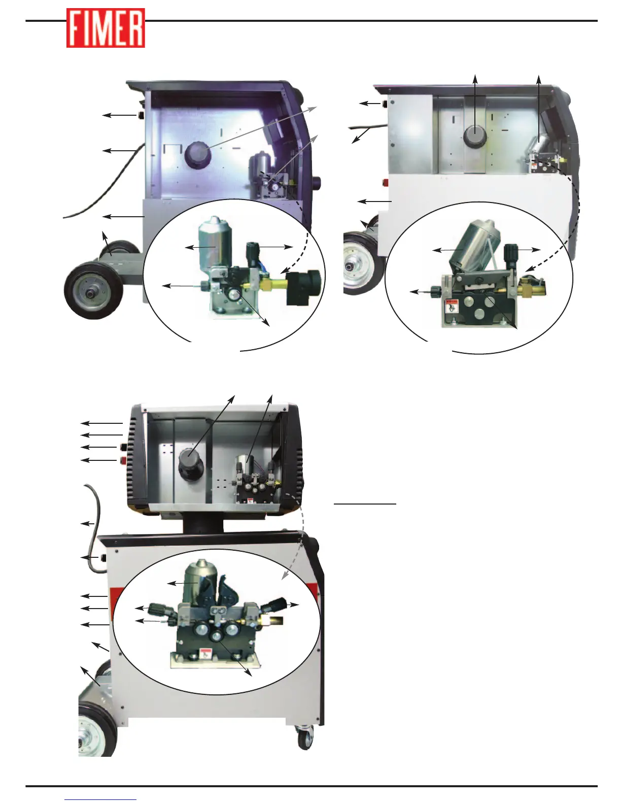
FIGURE 2
20. AIR INLET
21. GAS PIPE CONNECTOR: to be connected
to the pressure reducer of the cylinder
22. INPUT CABLE: connect this cable to the
mains power supply.
23. WIRE SPOOL
24. WIRE FEED UNIT: for more details refer to
Figure 2A.
25. SUPPORT FOR WELDING GAS CYLINDER.
26. WIRE ENTRANCE OF THE WIRE-FEED
MOTOR
27. WIRE PRESSURE REGULATOR: Allows
regulating the tension of the welding wire
28. WIRE-FEED MOTOR
29. WIRE-FEED ROLLERS
30. ELECTRICAL CONNECTOR FOR THE
SIGNALS (cable bundle) (separate trolley)
Fig. 2: SIDE VIEW
22
20
25
30
23 24
31
32
33, 34
22
21
35
36
20
37, 38
25
20