6
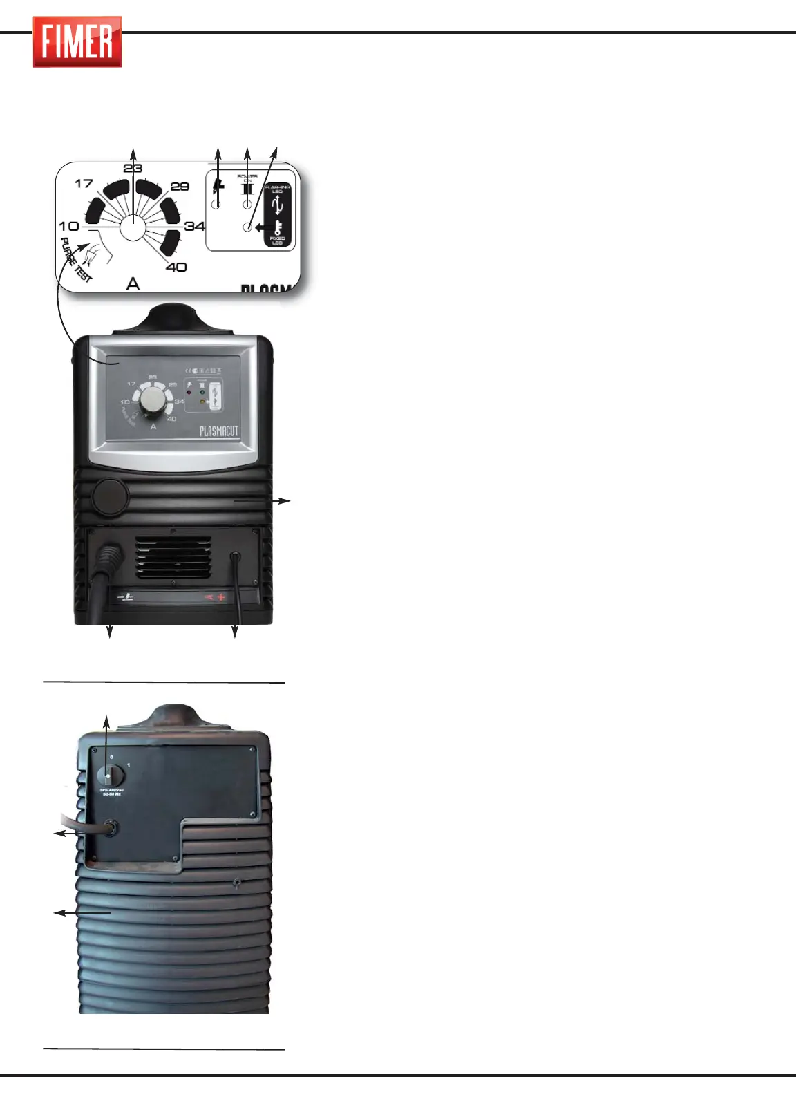
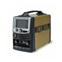
FIGURE 1:
1. Cutting current selector: A current ranging between 5A to
27A can be selected.
TP47K gen :5A min-40A max
2. Red LED: Lit when the pilot arc is present o when the shield
cup has not been secured (pulsante torcia premuto, ma arco
taglio non ancora innescato).
3. Green LED: Unit on
4. Yellow LED: Thermal protection indicating light.
This signal lights up when the machine is blocked due to
overheating.
This normally occurs when the machine’s intermittence factor has
been exceeded. Check that the air grills (19) positioned on the
back, front and sides of the machine are not obstructed and leave
the machine turned on to allow the internal components to cool
down; the normal cutting operations can be resumed once this
indicating light turns off.
5. Air Vent
6. Earth cable: Connects the earth clamp to the unit.
7. Cutting torch cable: Connects the torch to the unit.
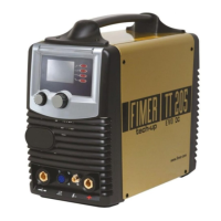
FIGURE 2:
8.
ON-OFF switch: turns the machine on and off.
9. INPUT CABLE: connection cable to the mains power equipped.
STATUS INDICATORS
3 Led green ON:
the unit is switched on and the power
supply is appropriate
.
2 Led red ON fixed + 4 Led yellow OFF:
the pilot arc has
been generated. (Beware! There is high voltage passing
through the torch.)
2 Led red ON fixed + 4 Led yellow ON fixed:
shield cup
alarm. Check and secure.
4 Led yellow ON fixed:
The unit has overheated. This
usually occurs when the intermittency factor has been
exceeded. Check the air vents (5) on the front and rear
panels of the unit and remove any blockages. Leave the
unit switched on to cool the internal components down.
Normal operations can be resumed once the LED goes
out.
4 Led yellow ON flashing:
Insufficient mains voltage.
Normal operations can resume as soon as the alarm
situations have been rectified.
The only alarm that does not automatically reset the unit
is the shield cup alarm. Once the shield cup has been
re-secured the unit must be switched OFF then ON again
to resume operations.
2. DESCRIPTION OF THE EQUIPMENT
Fig.1
Fig.2
8
9
5
6
7
1
5
23 4