9
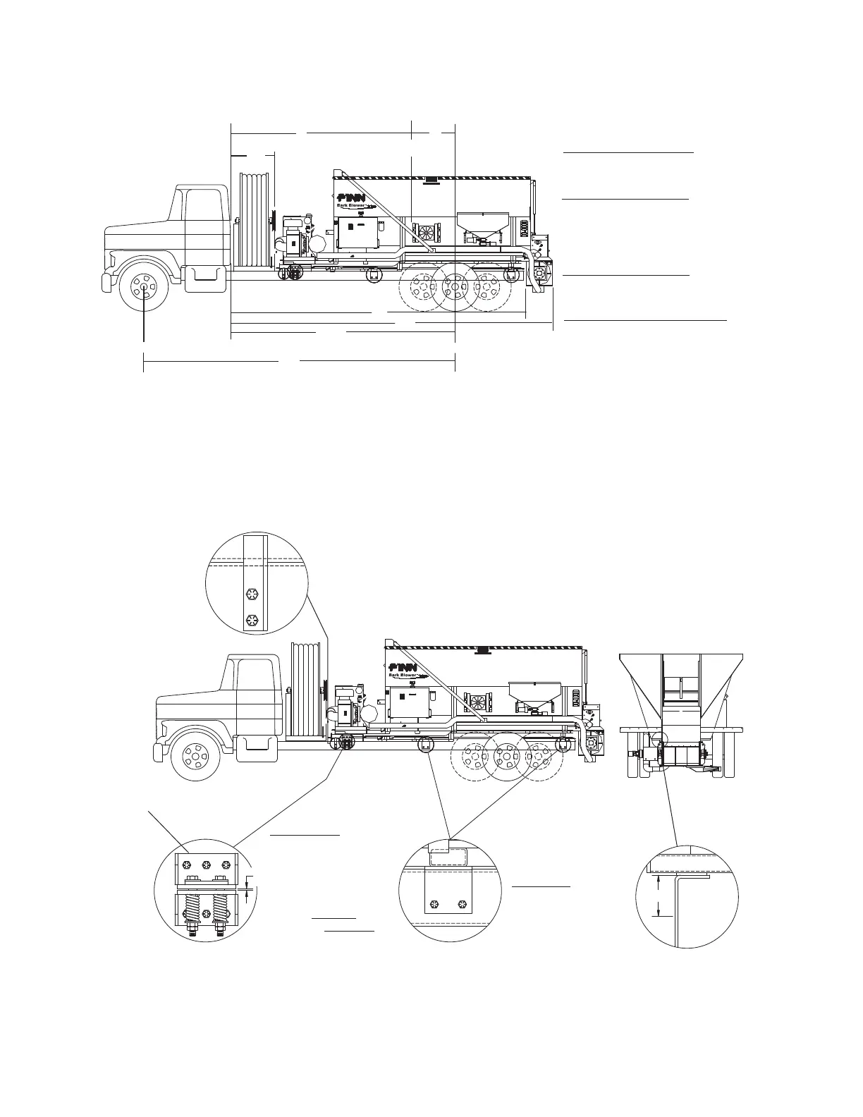
GENERAL MOUNTING GUIDELINES
(WB x FL) – (WB x FE) = G
BW
WB x (RE + HW - RL) = G
BW
G + C must be equal to or less than CA
(WB x FE) + (G x BW) = FL
WB
(WB x RE) + BW x (WB – G) = RL
WB
TRUCK MOUNTING CALCULATIONS
Body guides, of heavy angle, should be bolted or
welded to the truck frame near front end of the
Bark Blower engine base. This guide restricts lat-
eral movment of hopper and thus relieves shear
stress on mountings.
Slotted angle on top with 1/2"
thick cover strap.
IMPORTANT:
Ensure that tubes
are inserted to pre-
vent full compres-
sion of springs when
bolts are tightened.
5/8 in. Grade 8 bolt
and nuts.-All Places
Full length spacer thick
enough to cover rivet
heads; Drill clearnce
holes for rivet heads
where needed.
WARNING:
Do not weld or drill
truck frame in the
area.
Weld securely to Bark
Blower-bolt to truck
chassis
Figure 2
MOUNTING KIT
#11562
Figure 1
CF
OAL
CA/CT
RE
FE
RL
FL
WB
40
Ref.
C
BW
G
Center Of
Gravity
3/16
Gap.
2