2. CHANGE BURNER NOzzLES
INSTALLATION TIP: First remove all nozzles and then start replacing them. This will help to prevent the
pos-
si-
bility that some may not be
replaced.
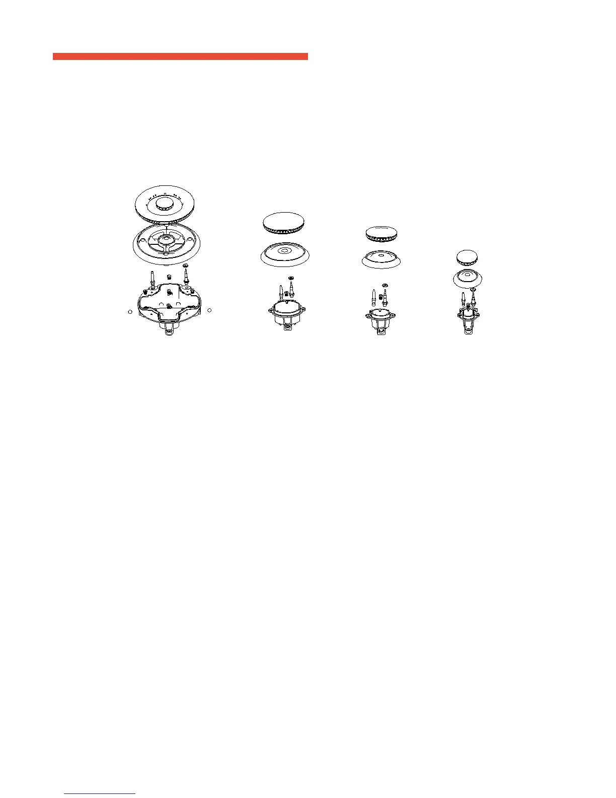
1. Remove the burner grates, burner caps and burner
heads.
2. Using a 7mm nut driver, remove the top burner nozzle. There are two nozzle per burner. The main orice is
locat-
ed below center of the burner, while the simmer nozzle is located higher beside the center of the
burner
Triple ring burner Rapid burner Semi-rapid burner Auxiliary
burner
IMPORTANT:
Orices must be located exactly as shown. Carefully read and observe each orice label for correct
location.
3. Install the proper nozzle in the exact locations as noted in the illustrations
above.
4. Return the natural gas nozzle to the bracket and reattach the bracket and the instruction sheet to the pressure
regu-
lator using the screw removed
previously.
5. Replace the burner bases, heads, caps and top
grates.
BURNER
POSITION NOZZLE
DIAMETER
MINIMUM
PRESSURE
MAXIMUM
PRESSURE
RATE
( BT U/H )
Auxiliary Front Right 1 x 0.70 10” 14” 4,800
Semi-Rapid Rear Left & Right 1 x 0.80 10” 14”
6,500
Rapid Front Left 1 x 0.89 10” 14” 8,500
Triple Ring Center 5 x 0.56 10” 14” 15,500
ATTENTION: BE SURE TO REVIEW AND OBSERVE EACH NOZZLE FOR CORRECT LOCATION
AND POSITION - PLEASE REFER TO FIGURE F and G BELOW:
FIGURE F
TRIPLE RING BURNER AUXILARY BURNER
5 NOZZLES SEMI-RAPID BURNER
RAPID BURNER
1 NOZZLE EACH
FIGURE G
Install the proper nozzles in the exact locations as noted in the illustrations above and the table below.
Replace the burner bases, heads, caps and top grates. Conrm burner caps are properly resting on the burner head.
LIQUID PRETROLEUM (LP) GAS NOZZLES
NOZZLES
56 5656
80
89 70
80
56
56
18 19
2. CHANGE bURNER NOZZLES
INSTA LLATION TIP: First remove all nozzles and then start replacing them. This will help to prevent the possi-
bility that some may not be replaced.
A. Remove the burner grates, burner caps and burner heads.
B. Using a 7mm nut driver, remove the top burner nozzle. There are two nozzle per burner. The main orice is locat-
ed below center of the burner, while the simmer nozzle is located higher beside the center of the burner
Triple ring burner Rapid burner Semi-rapid burner Auxiliary burner
IMPORTANT:
Orices must be located exactly as shown. Carefully read and observe each orice label for correct location.
C. Install the proper nozzle in the exact locations as noted in the illustrations above.
D. Return the natural gas nozzle to the bracket and reattach the bracket and the instruction sheet to the pressure regu-
lator using the screw removed previously.
E. Replace the burner bases, heads, caps and top grates.
 Loading...