Installation
MS-9050UD Series PN 52413:D 12/15/08 49
Before installing the module, place the disconnect switch to the right (disconnect) position to
prevent accidental activation of the municipal box. Note that a Disconnect LED will illuminate
after the module is installed in the MS-9050UD. In addition, the System Trouble LED will turn on
to indicate the Disconnect condition.
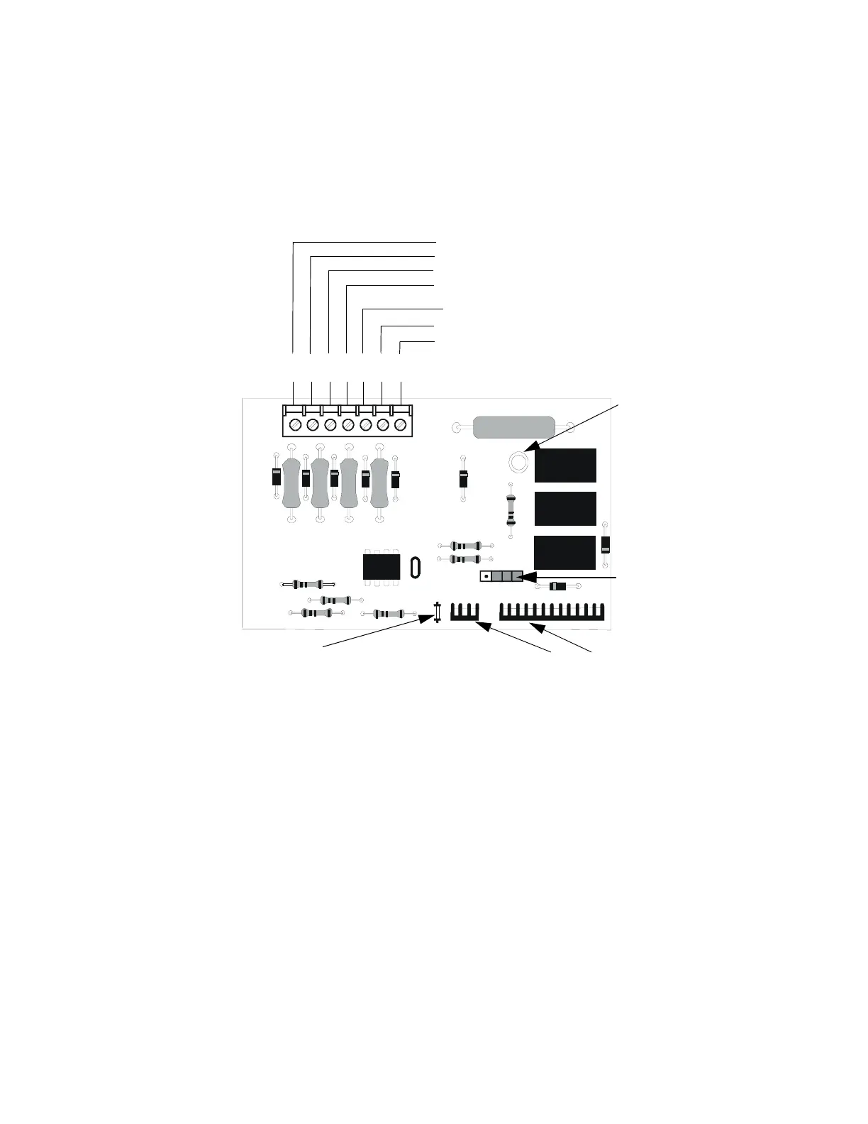
Figure 2.10 4XTMF Transmitter Module
Connect to FACP J8 & J9
Disconnect Switch
shown in disconnect
position
TBL Jumper
}Remote Alarm (power-limited)*
}Remote Trouble (power-limited)*
No connection
}Municipal Box (nonpower-limited)*
1 2 3 4 5 6 7
+ - + - + -
Polarities are shown for module activation
Note: 4XTMF Module is not directly suitable for transmitting reverse polarity
supervisory signal. For an application using reverse polarity of a supervisory
signal, refer to "FACP with Keltron" on page 195.
* Wiring from these
terminals can exit the
protected premises.
Dummy load terminals
6 and 7 (4.7kΩ, ¼ watt
resistor) if Municipal
Box is not connected.
Disconnect LED
4xtmfl.cdr