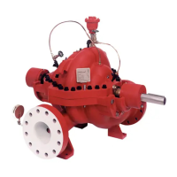
Series 8100/8150/8200/9100 Fire Pump
31 AC6102 Rev 03
10 Service
The procedures outlined in this section cover the dismantling
and reassembly of four different model types of Horizontal
Split Case fire pumps:
1. 8100
2. 8150
3. 8200
4. 9100
When working on the pump, use accepted mechanical
practices to avoid unnecessary damage to parts. Check
clearances and conditions of parts when pump is dismantled
and replace if necessary. Steps should usually be taken to
restore impeller and casing ring clearance when it exceeds
three times the original clearance.
WARNING
Rotating parts. Disconnect and lock out
power before servicing. Failure to follow
these instructions could result in serious
personal injury.
WARNING
Electrical Shock Hazard.
Disconnect and lock out power before servicing.
Failure to follow these instructions could result
in serious personal injury.
WARNING
During dismantling/assembly of the pump,
ensure that lifting devices are sufficiently
strong and that the pump-unit and parts are
secured to prevent tipping over. Failure to
follow these instructions could result in
serious personal injury and part damage.
CAUTION
Before dismantling the pump, ensure that
genuine AC-Fire Pump parts are available.
10.1 Tools required
In order to assemble and disassemble the pump, the
following tools are required:
Hex wrenches
Open end wrenches
Spanner wrench
Torque wrench with sockets
Feeler gauges
Range of screwdrivers
Soft mallet
Bearing pullers
Bearing induction heater
Allen wrenches
Dial indicators
Lifting sling
10.2 Dismantling
Refer to section 12, Replacement Parts, for exploded
drawings and parts lists. Part numbers listed in this procedure
refer to the 8100 series pumps; corresponding part numbers
for 8150, 8200, and 9100 can be identified by the description
in the parts lists.
10.2.1 Rotating Element
1. Isolate driver and lock out power supply in accordance
with local regulations.
2. Isolate suction and discharge valves.
3. Remove coupling guards and separate the coupling to
disconnect the pump from the driver.
4. Drain the pump by opening the vent plug [0-910-0] and
removing the drain plugs [0-910-0] on the suction and
discharge nozzles.
5. Remove flushlines [0-952-0], if supplied.
6. Series 8150, 8200, and 9100: Remove gland bolts [1-
904-9], washers [1-909-9], and slide gland [1-014-9]
away from the lower casing [2-001-8].
7. Remove all casing main joint cap screws [2-904-1] and
dowels [2-916-1].
8. Using the slot in the casing main joint, separate the
casing halves with a pry bar. Lift the upper half casing
[2-001-0] by the cast lugs.
NOTE: Some casings have jacking screws.
9. Series 8100 only: Tap the stuffing boxes [3-073-9] with
a soft-headed hammer to break the seal between the
stuffing box and the lower casing [2-001-0].
10. Series 8200 and 9100: Remove packing [1-924-9] and
seal cage [1-013-9] from each stuffing box.
11. Series 8150, 8200, and 9100: Remove cap screws [3-
904-9] which hold the bearing housings [3-025-3] to the
lower casing.
12. The rotating element may now be removed. Carefully lift
the complete rotating element, protecting the packing
surface on the outside diameter of the shaft sleeve [3-
009-9] from damage and place on two support blocks.
10.2.2 Bearing Housing
1. Remove four cap screws [3-904-9] from each bearing
housing [3-025-3, 3-025-4] and remove the bearing
housings from the shaft [3-007-0].
2. Bend back the lock-washer tab and remove locknut [3-
516-4] and lock-washer [3-517-4] from the outboard
end of the shaft and, using a bearing puller, remove the
bearing [3-026-4] from the shaft. Remove the inboard
end bearing [3-026-3] in the same manner.
NOTE: Locknut and lock-washer are not used on inboard
end bearings.
3. Series 8200 and 9100: Remove bearing covers [5-018-
0] out of bearing housings. Pull deflectors [3-136-9] off
the shaft. Slide stuffing box bushings [6-008-0] off the
shaft.
4. Series 8150 Remove the four capscrews [3-904-9] from
each bearing housing and remove the housings from
the bearing brackets. Remove the snap ring [3-177-3]
(outboard side only), bearings [3-026-2] and backing
snap rings [0-915-0]. Remove the bearing brackets from
the shaft.
10.2.3 Shaft seal – gland packing
1. Series 8100 Slide both stuffing boxes [3-073-9] off the
shaft, working deflector rings [3-136-9] off the shaft at
the same time.
2. Remove the lip seals [3-177-9] from the stuffing box.
3. Remove the gland bolts [1-904-9], gland halves [1-014-
9], packing [1-924-9] and, if supplied, seal cage [1-013-
9] from each stuffing box. Remove the O-rings [3-914-1]