AC6102 Rev 03 32
from the stuffing boxes.
10.2.4 Shaft sleeve
1. Loosen set screws [3-902-3] in shaft nuts [3-015-9] and
then remove shaft nuts using pin spanner wrench.
Remove O-rings [3-914-9] from the counter-bore in
shaft sleeve. Remove the shaft sleeves [3-009-2] from
the shaft.
10.2.5 Impeller and casing wear rings
1. The impeller and casing rings can now be removed if
required.
2. When removing the rotating element, the casing wear
rings [3-003-9] will be attached to the impeller [4-002-0]
by locking pins [3-943-9] inserted into the casing ring
and located in grooves in the lower half casing.
3. If impeller rings [0-004-0] are also fitted, they are shrunk
onto the impeller, and can be removed by cutting with a
cold chisel.
10.3 Examination of parts
CAUTION
Used parts must be inspected before
assembly to ensure that the pump will
operate correctly.
10.3.1 Casing and impeller
Inspect for excessive wear, pitting, corrosion, erosion or
damage and any sealing surface irregularities. Replace as
necessary.
10.3.2 Shaft and sleeve
Replace if grooved, pitted or worn.
10.3.3 Gaskets and O-rings
After dismantling, discard and replace.
10.3.4 Bearings
CAUTION
Do not reuse the ball bearings.
It is recommended that bearings are not reused after
removal from the shaft.
10.3.5 Bearing isolators and lip seals
1. The lubricant, bearings and bearing housing seals are
to be inspected for contamination and damage.
Damaged parts should be replaced.
2. If bearing damage is not due to normal wear and the
lubricant contains adverse contaminants, the cause
should be corrected before the pump is returned to
service.
3. Bearing isolators (if used) should be inspected for
damage but are normally non-wearing parts and can be
usually reused.
10.4 Assembly
Refer to section 12, Replacement Parts, for exploded
drawings and parts lists. Part numbers listed in this procedure
refer to the 8100 series pumps; corresponding part numbers
for 8200 and 9100 can be identified by the description in the
parts lists.
10.4.1 Wear Rings
1. Impeller rings [0-004-0] (when fitted) should be heated
up to approximately 300°F - 400°F [150°C - 200°C] and
then slipped onto the impeller. Using gloves hold rings
against the impeller shoulder until they cool.
2. Slide the casing rings [3-003-9] over the impeller hubs
before mounting the rotating element into the lower
casing, ensuring that the locking pins in the rings locate
into the grooves in the casing.
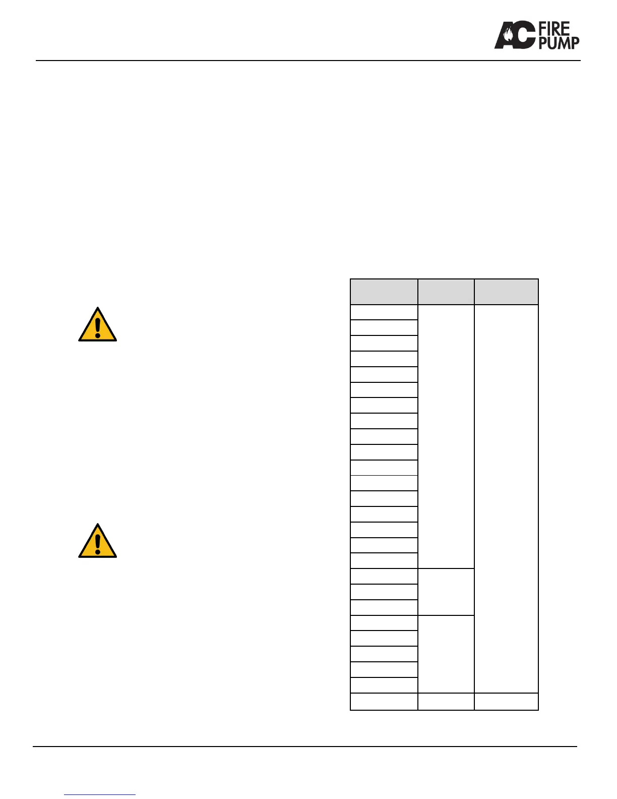
3. Check the wear ring clearance against the appropriate
pump size in Table 8.
Pump Size Series/Type
Wear Ring
Clearance in
[mm]
3X2X11F-S
8100
0.015 - 0.017
[0.38 – 0.43]
6X4X9F
6X4X10F-M
6X4X11F
6X4X12F
6X6X9F
8X6X9F
8X6X10F
8X6X12F
8X6X12F-M
8X6X13F
8X6X18F
8X8X12F
8X8X17F
10X8X17F
10X8X20F
12X10X18F
8x6x14F-S
8200
8X6X14F-L
8x6x18F
12X8X21F
9100
12X8X22F-M
14X10X20F
16X12X23F
14X10X20F-L
16X10X22F 8150
.019-.021
[.48-.53]
Table 8 Wear ring clearance