INTRODUCTION TO COMBI
OPERATIONS
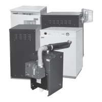
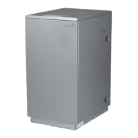
FIREBIRD COMBI C
The Firebird Combi C is designed to give separate
control to both the domestic hot water and to the
central heating. The Combi C has three thermistors
connected to a PCB board that gives very accurate
and fast temperature control and one high limit
thermostats that help to achieve this.
Tank thermistor
The Tank Thermistor controls the temperature of
the heat store (or Slave Tank). The Tank Thermistor
sensor is located in stat pocket in the top of the tank
at the side of the boiler. When the thermistor senses
that the heat store is seeking heat it activates a relay
on the PCB. board in the control panel this in turn
sends power to the domestic circulating pump and
burner.
The Flow sensor is the only other device that will
activates the relay in this way when it detects the
flow of water on opening a tap. This heat store is
a tank with a bank of water stored at a higher
temperature than that normally used on a central
heating circuit, and is used for domestic hot water
production. The temperature of this heat store has
priority over central heating. Central heating will not
work until the heat store reaches a temperature of
78°C.
The Boiler Control thermistor
The boiler Control thermistor has a number of
functions.
1. It controlling the temperature of the water in the
boiler when in central heating mode (60°C to 80°C).
The sensor from this thermistor is situated in stat
pocket in the boiler.
2. The over heat function activates the domestic
circulating pump when due to residual heat rise in the
boiler, the temperature reaches 93°C. The water is
circulated from the boiler into the heat store tank
thus preventing the boiler from activating the high
limit
thermistor.
3. The early alert function controls the burner when
the Combi is operating in domestic hot water mode.
If the temperature in the boiler reaches 87°C before
the tank thermostat cuts out, the early alert
thermistor cuts off the burner.
Firebird Enviromax Condensing Range
2
11
HOUSEHOLDER
The High Limit Thermostat
The High limit thermostat cuts off power supply to
the burner should all thermostats fail. It is a manual
re-set thermostat, and will stay off until such time
that it is re set. If this thermostat is activated, the
reason for activating must be resolved before
re-setting. The sensor from this thermostat is situated
in stat pocket in the boiler in the same Thermostat
pocket as the boiler control thermistor. The re-set
button is located under the control panel directly
behind the location for the optional DWH timer. See
Control Panel Diagram - on page 22 & 30.
Flow Switch thermistor
The flow switch thermistor is colored red and is
positioned in a pocket on the cold feed pipe to the
plate heat exchanger. When the thermistor senses a
drop in temperature with the flowof water on
opening a tap it activates a relay on the PCB. board,
this in turn sends power to the domestic circulating
pump and burner.
Important
The thermistor sensor wires are secured to the lid of
the control panel and to the casing of the combi, this
is ensure that the thermistor sensor wires are kept
separate from mains power cables. i.e.: Mains feed
cable to combi and circulating pump cables
 Loading...